STK672-640C-E View Datasheet(PDF) - ON Semiconductor
Part Name
Description
Manufacturer
STK672-640C-E Datasheet PDF : 27 Pages
| |||
Precautions
STK672-640C-E
[GND wiring]
• To reduce noise on the 5V system, be sure to place the GND of C01 in the circuit given above as close as possible to
Pin 2 and Pin 6 of the hybrid IC. Also, to achieve accurate current settings, be sure to connect Vref GND to the point
where P.G1 and P.G2 share a connection.
[Input pins]
• If VDD is being applied, use care that each input pin does not apply a negative voltage less than -0.3V to PG and DO
not apply a voltage greater than or equal to VDD voltage.
• Do not wire by connecting the circuit pattern on the P.C.B side to N.C Pins. shown in the internal block diagram.
• Apply 2.5V high level input to pins 10, 12, 13, 14, 15, and 17.
• Since the input pins do not have built-in pull-up resistors, when the open-collector type pins 10, 12, 13, 14, 15, and 17
are used as inputs, a 1 to 20kΩ pull-up resistor (to VDD) must be used.
At this time, use a device for the open collector driver that has output current specifications that pull the voltage down
to less than 0.8V at Low level (less than 0.8V at Low level when IOL=5mA).
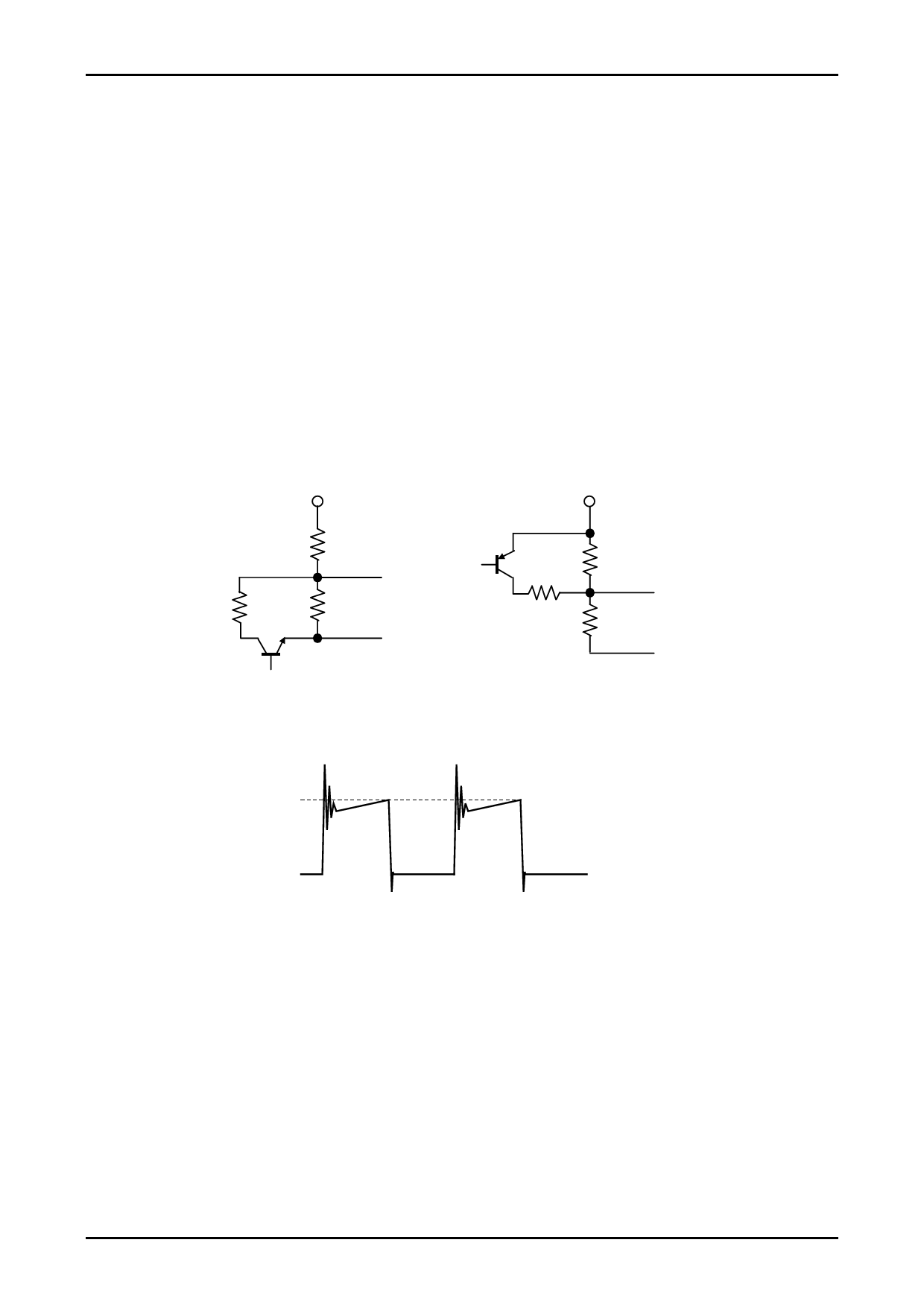
[Current setting Vref]
If the motor current is temporarily reduced, the circuit given below (STK672-640C-E : IOH>0.3A) is recommended.
5V
R01
Vref
R3
R02
5V
R01
Vref
R3
R02
• Motor current peak value IOH setting
IOH
0
IOH=(Vref÷4.9) ÷Rs
The value of 4.9 in Equation above represents the Vref voltage as divided by a circuit inside the control IC.
Vref=(R02÷ (R01+R02)) ×5V(or 3.3V)
Rs is an internal current detection resistor value of the hybrid IC.
Rs=0.089Ω when using the STK672-640C-E
No. A2116-6/27
Share Link: 