LA4183 View Datasheet(PDF) - SANYO -> Panasonic
Part Name
Description
Manufacturer
LA4183 Datasheet PDF : 11 Pages
| |||
LA4183
Description of External Parts
C1 (C2)
Feedback capacitor
C3 (C4)
C5 (C6)
C7 (C8)
Bootstrap capacitor
Oscillation preventing capacitor
Output capacitor
C9
Decoupling capacitor
C10
Power source capacitor
The low-range cut-off frequency is determined by the following formula:
fL = 1 / (2 π C1vRf), fL: Low-range cut-off frequency
Rf: Feedback resistor
(50 Ω embedded + Rf externally connected)
The frequency, however, affects the starting time in conjuction with
decoupling capacitors. Therefore, it is necessary to determine it after a
full review of the required low-frequency range and other similar
conditions.
The output at low frequencies depends on this capacitor. If the capacity
is decreased, the output at low frequencies goes lower. 47 µF min. is
required.
Use polyester film capacitor which is good in temperature characteristic
and frequency characteristic. Aluminum electrolytic capacitor or
ceramic capacitor causes oscillation at low temperatures.
The low-range cut-off frequency is determined by the following formula.
fL = 1 / (2π C7vRL), fL: Low-range cut-off frequency
RL:Load resistance
When using bridge-connected, double the capacitance to obtain
equivalent low-range frequency characteristics to those in a 2-channel
application.
Used for the ripple filter. Since the rejection effect is saturated at a
certain capacity, it is meaningless to increase the capacity more than
needed.
This capacitor, being also used for the time constant of the muting
circuit, affects the starting time.
Application Circuits
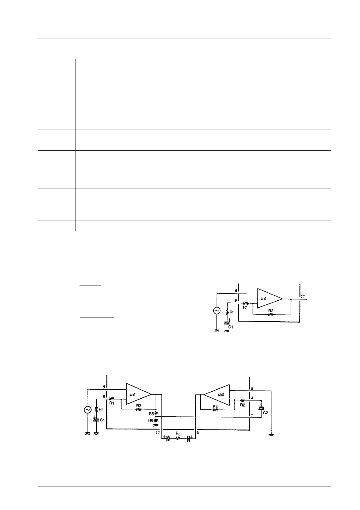
1. Voltage gain adjustment
. Stereo
The voltage gain depends on built-in-resistors R1 (R2), R3 (R4) as follows:
R3 (R4)
VG = 20 log
R1 (R2)
[dB]
If the IC is used at a voltage gain less than this, the following
equation with Rf added applies.
R3 (R4)
VG = 20 log R1 (R2) + Rf [dB]
where R1 (R2) = 50 Ω typ.,
R3 (R4) = 10 kΩ typ.
. Bridge
The following shows the bridge amplifier configuration, where ch1 operates as a non-inverting amplifier and ch2 as an inverting
amplifier.
No.887-4/11
Share Link: 