ADSP-21160M(Rev0) View Datasheet(PDF) - Analog Devices
Part Name
Description
Manufacturer
ADSP-21160M Datasheet PDF : 52 Pages
| |||
ADSP-21160M
$'63[
$'63[
$'63[
$'63[
&/.,1
5(6(7
$''5±
' $7 $ ±
53%$
,'±
&21752/
3$
%5± %5±
%5
$'63[
&/.,1
5(6(7
$ '' 5 ±
' $7 $ ±
53%$
,'±
&21752/
3$
%5 %5±
%5
$'63[
&/.,1
5(6(7
$''5±
' $7 $ ±
53%$
,'±
5';
:5;
$&.
0 6 ±
5(6(7
&/2&.
%06
3$*(
6%76
&/.287
&6
+%5
+%*
5('<
&21752/
3$
%5±
%5
*/2%$/
0(025<
$1'
3( 5,3+ ( 5 $/ 6
23 7,21 $/
$''5
'$7$
2(
:(
$&.
&6
&6
$''5
'$7$
%227 (3520
23 7,21 $/
+267
352&( 6625
,1 7(5 )$&(
23 7,21 $/
$''5
'$7$
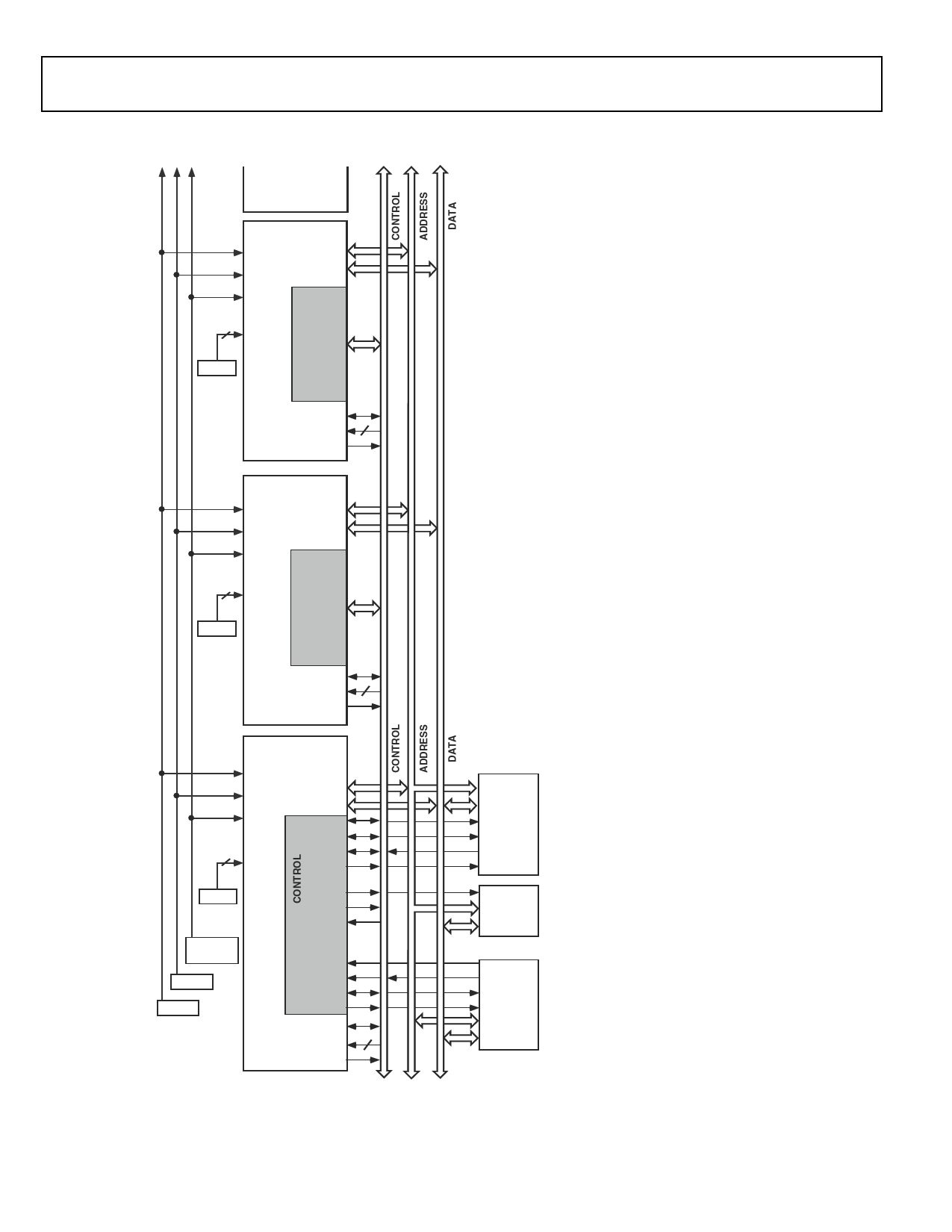
Figure 4. Shared Memory Multiprocessing System
transmit and receive functions provide greater flexibility for
serial communications. Serial port data can be automati-
cally transferred to and from on-chip memory via a
dedicated DMA. Each of the serial ports offers a TDM
multichannel mode. The serial ports can operate with lit-
tle-endian or big-endian transmission formats, with word
lengths selectable from 3 bits to 32 bits. They offer selectable
synchronization and transmit modes as well as optional
µ-law or A-law companding. Serial port clocks and frame
syncs can be internally or externally generated.
Host Processor Interface
The ADSP-21160M host interface allows easy connection
to standard microprocessor buses, both 16-bit and 32-bit,
with little additional hardware required. The host interface
is accessed through the ADSP-21160M’s external port and
is memory-mapped into the unified address space. Four
channels of DMA are available for the host interface; code
and data transfers are accomplished with low software
overhead. The host processor communicates with the
ADSP-21160M’s external bus with host bus request
(HBR), host but grant (HBG), ready (REDY), acknowledge
(ACK), and chip select (CS) signals. The host can directly
read and write the internal memory of the ADSP-21160M,
and can access the DMA channel setup and mailbox regis-
ters. Vector interrupt support provides efficient execution
of host commands.
Program Booting
The internal memory of the ADSP-21160M can be booted
at system power-up from an 8-bit EPROM, a host proces-
sor, or through one of the link ports. Selection of the boot
source is controlled by the BMS (Boot Memory Select),
EBOOT (EPROM Boot), and LBOOT (Link/Host Boot)
pins. 32-bit and 16-bit host processors can be used
for booting.
Phased Locked Loop
The ADSP-21160M uses an on-chip PLL to generate the
internal clock for the core. Ratios of 2:1, 3:1, and 4:1
between the core and CLKIN are supported. The
CLK_CFG pins are used to select the ratio. The CLKIN
rate is the rate at which the synchronous external
port operates.
Power Supplies
The ADSP-21160M has separate power supply connections
for the internal (VDDINT), external (VDDEXT), and analog
(AVDD/AGND) power supplies. The internal and analog
supplies must meet the 2.5 V requirement. The external
supply must meet the 3.3 Vrequirement. All external supply
pins must be connected to the same supply.
Note that the analog supply (AVDD) powers the
ADSP-21160M’s clock generator PLL. To produce a stable
clock, the system must provide an external circuit to filter
the power input to the AVDD pin. Place the filter as close as
possible to the pin. For an example circuit, see Figure 5. To
prevent noise coupling, use a wide trace for the analog
ground (AGND) signal and install a decoupling capacitor
as close as possible to the pin.
–6–
REV. 0
Share Link: 