MPSW14 View Datasheet(PDF) - ON Semiconductor
Part Name
Description
Manufacturer
MPSW14 Datasheet PDF : 3 Pages
| |||
MPSW13 MPSW14
ELECTRICAL CHARACTERISTICS (TA = 25°C unless otherwise noted) (Continued)
Characteristic
Symbol
Min
Max
ON CHARACTERISTICS(1)
DC Current Gain
(IC = 10 mAdc, VCE = 5.0 Vdc)
MPSW13
MPSW14
hFE
5,000
—
10,000
—
(IC = 100 mAdc, VCE = 5.0 Vdc)
Collector−Emitter Saturation Voltage
(IC = 100 mAdc, IB = 0.1 mAdc)
Base−Emitter On Voltage
(IC = 100 mAdc, VCE = 5.0 Vdc)
SMALL−SIGNAL CHARACTERISTICS
Current−Gain — Bandwidth Product(2)
(IC = 10 mAdc, VCE = 5.0 Vdc, f = 100 MHz)
1. Pulse Test: Pulse Width v 300 ms, Duty Cycle v 2.0%.
2. fT = |hfe| • ftest.
MPSW13
MPSW14
10,000
—
20,000
—
VCE(sat)
—
1.5
VBE(on)
—
2.0
fT
125
—
Unit
—
Vdc
Vdc
MHz
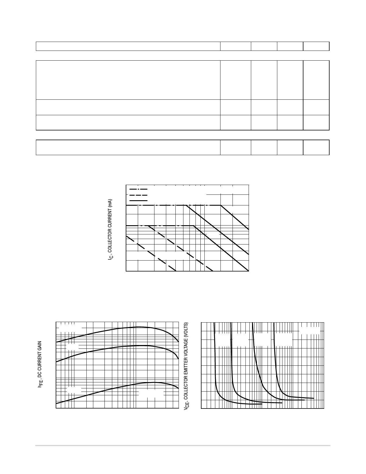
CURRENT LIMIT
3.0 k
THERMAL LIMIT
DUTY CYCLE ≤ 10%
SECOND BREAKDOWN LIMIT
2.0 k
100 ms
1.0 ms
1.0 k
1.0 s
500
TA = 25°C
TC = 25°C
200
1.5 2.0
5.0
10
20 30
VCE, COLLECTOR-EMITTER VOLTAGE (VOLTS)
Figure 1. Active Region — Safe Operating Area
200 k
100 k
70 k
50 k
TJ = 125°C
25°C
30 k
20 k
10 k
7.0 k
5.0 k
-55°C
3.0 k
2.0 k
5.0 7.0 10
VCE = 5.0 V
20 30 50 70 100 200 300 500
IC, COLLECTOR CURRENT (mA)
Figure 2. DC Current Gain
3.0
TJ = 25°C
2.5
IC = IC =
10 mA 50 mA
IC =
IC =
250 mA 500 mA
2.0
1.5
1.0
0.5
0.1 0.2
0.5 1.0 2.0 5.0 10 20 50 100 200 500 1000
IB, BASE CURRENT (mA)
Figure 3. Collector Saturation Region
http://onsemi.com
1325
Share Link: 