ICS9341F View Datasheet(PDF) - Integrated Circuit Systems
Part Name
Description
Manufacturer
ICS9341F Datasheet PDF : 9 Pages
| |||
ICS9341
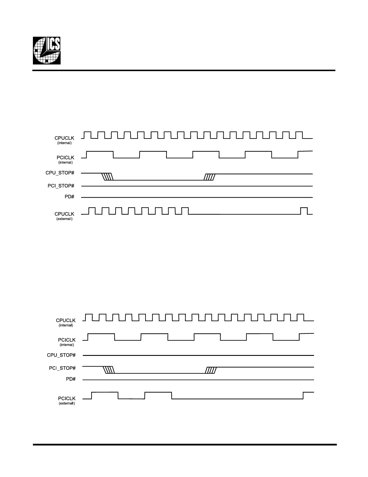
CPU_STOP# Timing Diagram
CPU_STOP# is an asynchronous input to the clock synthesizer. It is used to turn off the CPU and 3V66 clocks for low power
operation. CPU_STOP# is asserted asynchronously by the external clock control logic with the rising edge of free running PCI
clock (and hence CPU clock) and must be internally synchronized to the external output. All other clocks will continue to run
while the CPU clocks are disabled. The CPU clocks must always be stopped in a low state and started in such a manner as to
guarantee that the high pulse width is a full pulse.
Notes:
1. All timing is referenced to the internal CPUCLK.
2. The internal label means inside the chip and is a reference only. This in fact may not be the way that the control is designed.
3. PD# and PCI_STOP# are shown in a high state.
PCI_STOP# Timing Diagram
PCI_STOP# is an input to the clock synthesizer. It is used to turn off the PCI clocks for low power operation. PCI clocks are
required to be stopped in a low state and started such that a full high pulse width is guaranteed. ONLY one rising edge of
PCICLK_F is allowed after the clock control logic switched for the PCI outputs to become enabled/disabled.
Notes:
1. All timing is referenced to CPUCLK.
2. Internal means inside the chip.
3. All other clocks continue to run undisturbed.
4. PD# and CPU_STOP# are shown in a high state.
5
Share Link: 