AV9248F-65 View Datasheet(PDF) - Integrated Circuit Systems
Part Name
Description
Manufacturer
AV9248F-65 Datasheet PDF : 10 Pages
| |||
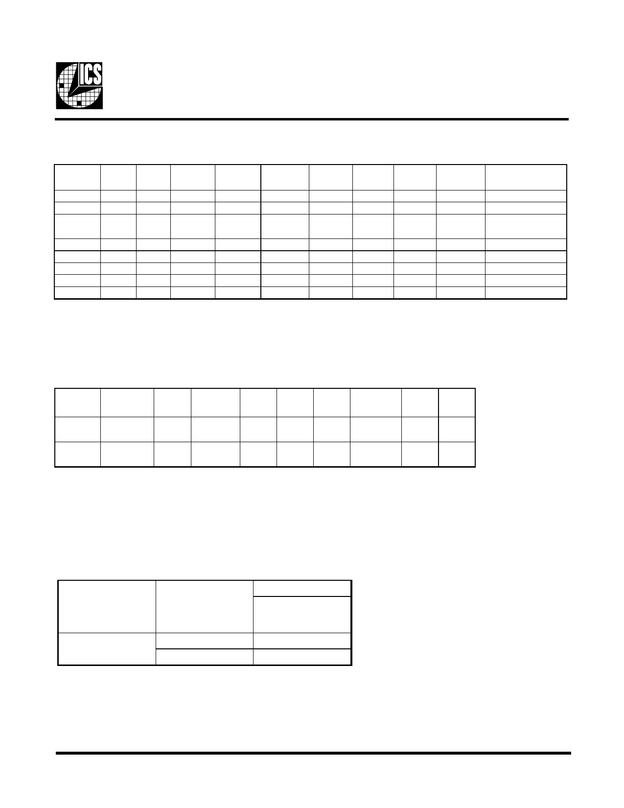
ICS9248-65
Frequency Select:
SEL
133/100#
0
0
SEL1
0
0
SEL0
0
1
CPU
MHz
Hi-Z
N/A
CPU/2
MHz
Hi-Z
N/A
3V66
MHz
Hi-Z
N/A
PCI
MHz
Hi-Z
N/A
48
MHz
Hi-Z
N/A
REF
MHz
Hi-Z
N/A
IOAPIC
MHz
Hi-Z
N/A
0
1
0
100
50
66.6 33.3 Hi-Z 14.318 16.67
0
1
1
100
50
66.6 33.3 48 14.318 16.67
1
0
0 TCLK/2 TCLK/4 TCLK/4 TCLK/8 TCLK/2 TCLK TCLK/16
1
0
1
N/A
N/A
N/A
N/A N/A N/A
N/A
1
1
0 133.3
66
66
33 Hi-Z 14.318 16.67
1
1
1 133.3 66
66
33
48 14.318 16.67
Comments
Tri-state
Reserved
48MHz PLL
disabled
Test mode (1)
Reserved
Note:
1. TCLK is a test clock driven on the x1 input during test mode.
ICS9248-65 Power Management Features:
PD#
CPUCLK CPU/2 IOAPIC 3V66
PCI
PCI_F
REF.
48MHz
0
LOW LOW LOW LOW LOW LOW LOW
Osc VCOs
OFF OFF
1
ON
ON ON ON ON ON
ON
ON ON
Note:
1. LOW means outputs held static LOW as per latency requirement next page.
2. On means active.
3. PD# pulled Low, impacts all outputs including REF and 48 MHz outputs.
Power Management Requirements:
Singal
Singal State
Latency
No. of rising edges
of PCICLK
1 (normal operation)
PD#
0 (power down)
3mS
2max.
Note:
1. Clock on/off latency is defined in the number of rising edges of free running PCICLKs between the clock disable goes low/
high to the first valid clock comes out of the device.
2. Power up latency is when PWR_DWN# goes inactive (high to when the first valid clocks are dirven from the device.
3
Share Link: 