IDT79R4650133MS(1996) View Datasheet(PDF) - Integrated Device Technology
Part Name
Description
Manufacturer
IDT79R4650133MS Datasheet PDF : 22 Pages
| |||
IDT79R4650
COMMERCIAL TEMPERATURE RANGE
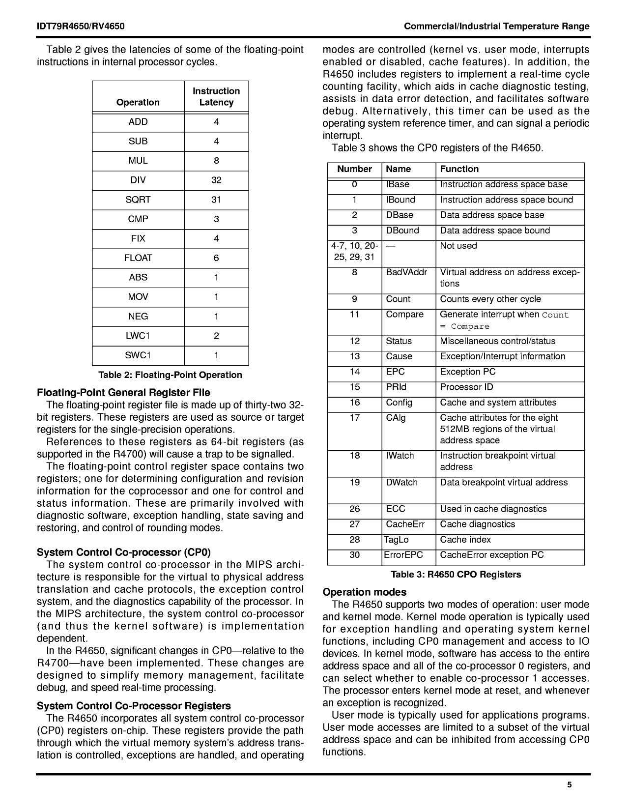
Table 2 gives the latencies of some of the floating-point
instructions in internal processor cycles.
Operation
Instruction
Latency
ADD
4
SUB
4
MUL
8
DIV
32
SQRT
31
CMP
3
FIX
4
FLOAT
6
ABS
1
MOV
1
NEG
1
LWC1
2
SWC1
1
Table 2: Floating-Point Operation
Floating-Point General Register File
The floating-point register file is made up of thirty-two 32-
bit registers. These registers are used as source or target
registers for the single-precision operations.
References to these registers as 64-bit registers (as
supported in the R4600) will cause a trap to be signalled to
the integer unit.
The floating-point control register space contains two
registers; one for determining configuration and revision
information for the coprocessor and one for control and
status information. These are primarily involved with
diagnostic software, exception handling, state saving and
restoring, and control of rounding modes.
lation is controlled, exceptions are handled, and operating
modes are controlled (kernel vs. user mode, interrupts
enabled or disabled, cache features). In addition, the
R4650 includes registers to implement a real-time cycle
counting facility, which aids in cache diagnostic testing,
assists in data error detection, and facilitates software
debug. Alternatively, this timer can be used as the
operating system reference timer, and can signal a periodic
interrupt.
Table 3 shows the CP0 registers of the R4650.
Number Name
0
IBase
1
IBound
2
DBase
3
DBound
4-7, 10, 20- —
25, 29, 31
8
BadVAddr
9
Count
11
Compare
12
Status
13
Cause
14
EPC
15
PRId
16
Config
17
CAlg
18
IWatch
19
DWatch
Function
Instruction address space base
(new in R4650)
Instruction address space bound
(new in R4650)
Data address space base (new in
R4650)
Data address space bound (new in
R4650)
Not used
Virtual address on address excep-
tions
Counts every other cycle
Generate interrupt when Count
= Compare
Miscellaneous control/status
Exception/Interrupt information
Exception PC
Processor ID
Cache and system attributes
Cache attributes for the eight
512MB regions of the virtual
address space — new register
Instruction breakpoint virtual
address
Data breakpoint virtual address
System Control Co-processor (CP0)
The system control co-processor in the MIPS archi-
tecture is responsible for the virtual to physical address
translation and cache protocols, the exception control
system, and the diagnostics capability of the processor. In
the MIPS architecture, the system control co-processor
(and thus the kernel software) is implementation
dependent.
In the R4650, significant changes in CP0 relative to the
R4600 have been implemented. These changes are
designed to simplify memory management, facilitate
debug, and speed real-time processing.
System Control Co-Processor Registers
The R4650 incorporates all system control co-processor
(CP0) registers on-chip. These registers provide the path
through which the virtual memory system’s address trans-
26
ECC
Used in cache diagnostics
27
CacheErr Cache diagnostics
28
TagLo
Cache index
30
ErrorEPC CacheError exception PC
Table 3: R4650 CPO Registers
Operation modes
The R4650 supports two modes of operation: user mode
and kernel mode.
Kernel mode operation is typically used for exception
handling and operating system kernel functions, including
CP0 management and access to IO devices. In kernel
mode, software has access to the entire address space
and all of the co-processor 0 registers, and can select
whether to enable co-processor 1 accesses. The processor
5.8
5
Share Link: 