LH28F008SC View Datasheet(PDF) - Sharp Electronics
Part Name
Description
Manufacturer
LH28F008SC Datasheet PDF : 38 Pages
| |||
8M (1M √ó 8) Flash Memory
LH28F008SC
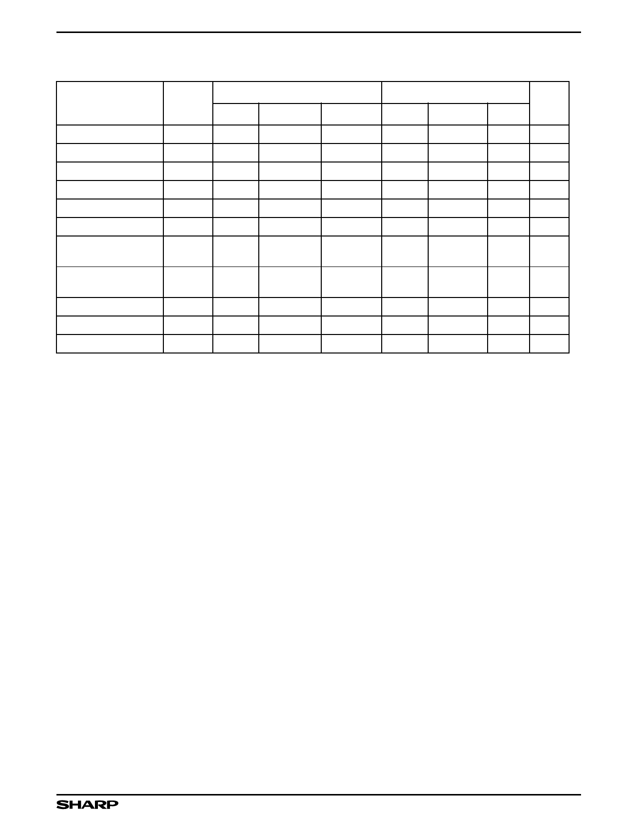
Command Definitions9
COMMAND
Read Array/Reset
Read Identifier Codes
Read Status Register
Clear Status Register
Block Erase
Byte Write
Block Erase and Byte
Write Suspend
Block Erase and Byte
Write Resume
Set Block Lock-Bit
Set Master Lock-Bit
Clear Block Lock Bits
BUS
CYCLES
REQ'D
1
‚â•2
2
1
2
2
1
1
2
2
2
FIRST BUS CYCLE
OPER.1 ADDRESS2
DATA3
Write
X
FFH
Write
X
90H
Write
X
70H
Write
X
50H
Write
BA
20H
Write
WA
40H or 10H
Write
X
B0H
Write
X
D0H
Write
BA
60H
Write
X
60H
Write
X
60H
SECOND BUS CYCLE
OPER.1 ADDRESS2 DATA3
Read
IA
ID
Read
X
SRD
Write
BA
D0H
Write
WD
WA
Write
BA
01H
Write
X
F1H
Write
X
D0H
NOTE
4
5
5, 6
5
5
7
7
8
NOTES:
1. Bus operations are defined in Bus Definition Table.
2. X = Any valid address within the device.
IA = Idendifier Code Address: see Figure 5.
BA = Address within the block being erased or locked.
WA = Address of memory location to be written.
3. SRD = Data read from status register. See Status Register for a description of the status register bits.
WD = Data to be written at location WA. Data is latched on the rising edge of WE » or CE » (whichever goes high first).
ID = Data read from identifier codes.
4. Following the Read Identifier Codes command, read operations access manufacturer, device, block lock, and master lock codes.
See Read Identifier Code Command Section for read identifier code data.
5. If the block is locked, RP » must be at VHH to enable block erase or byte write operations. Attempts to issue a block erase or byte
write to locked block while RP » is VIH.
6. Either 40H or 10H are recognized by the WSM as the byte write setup.
7. If the master lock-bit is set, RP » must be at VHH to set a block lock-bit. RP » must be at VHH to set the master lock-bit. If the master
lock-bit is not set, a block lock-bit can be set while RP » is VIH.
8. If the master lock-bit is set, RP » must be at VHH to clear block lock-bits. The clear block lock-bits operation simultaneously clears all
block lock-bits. If the master lock-bit is not set, the Clear Block Lock-Bits command can be done while RP » is VIH.
9. Commands other than those shown above are reserved by SHARP for future device implementations and should not be used.
9
Share Link: 