AT89LP4052-20XU(2008) View Datasheet(PDF) - Atmel Corporation
Part Name
Description
Manufacturer
AT89LP4052-20XU Datasheet PDF : 93 Pages
| |||
7.7 I/O Ports
7.8 Reset
The I/O ports of the AT89LP2052/LP4052 may be configured in four different modes. On the
AT89LP2052/LP4052, all the I/O ports revert to input-only (tri-stated) mode at power-up or reset.
In the standard 8051, all ports are weakly pulled high during power-up or reset. To enable 8051-
like ports, the ports must be put into quasi-bidirectional mode by clearing the P1M0 and P3M0
SFRs.
The RST pin in the AT89LP2052/LP4052 has different pulse width requirements than the stan-
dard 8051. The RST pin is sampled every clock cycle and must be held high for a minimum of
two clock cycles, instead of 24 clock cycles, to be recognized as a valid reset pulse
8. Enhanced CPU
The AT89LP2052/LP4052 uses an enhanced 8051 CPU that runs at 6 to 12 times the speed of
standard 8051 devices (or 3 to 6 times the speed of X2-mode 8051 devices). The increase in
performance is due to two factors. First, the CPU fetches one instruction byte from the code
memory every clock cycle. Second, the CPU uses a simple two-stage pipeline to fetch and exe-
cute instructions in parallel. This basic pipelining concept allows the CPU to obtain up to 1 MIPS
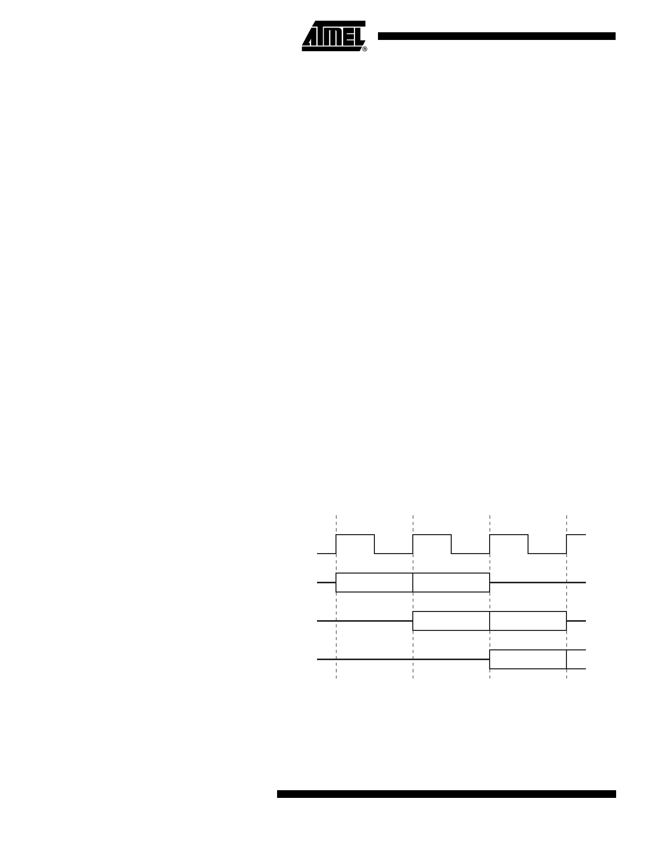
per MHz. A simple example is shown in Figure 8-1.
The MCS-51 instruction set allows for instructions of variable length from 1 to 3 bytes. In a sin-
gle-clock-per-byte-fetch system this means each instruction takes at least as many clocks as it
has bytes to execute. A majority of the instructions in the AT89LP2052/LP4052 follow this rule:
the instruction execution time in clock cycles equals the number of bytes per instruction with a
few exceptions. Branches and Calls require an additional cycle to compute the target address
and some other complex instructions require multiple cycles. See Section 22. “Instruction Set
Summary” on page 51 for more detailed information on individual instructions. Figures 8-2 and
8-3 show examples of one- and two-byte instructions.
Figure 8-1. Parallel Instruction Fetches and Executions
Tn
Tn+1
Tn+2
System Clock
nth Instruction
Fetch
Execute
(n+1)th Instruction
Fetch
Execute
(n+2)th Instruction
Fetch
8 AT89LP2052/LP4052
3547I–MICRO–6/08
Share Link: 