ATS-15E-99-C2-R0 View Datasheet(PDF) - Advanced Thermal Solutions, Inc.
Part Name
Description
Manufacturer
ATS-15E-99-C2-R0 Datasheet PDF : 1 Pages
| |||
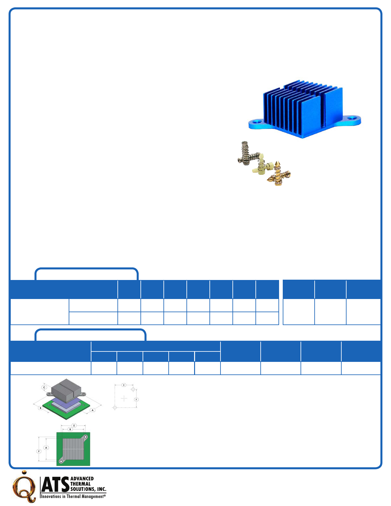
pushPIN™ Heat Sink Assembly
ATS Part#: ATS-15E-99-C2-R0
Description: pushPIN™ HS ASMBLY,FINE-PITCH,STRAIGHT, HOLE PATTERN:RIGHT-TABBED,BLUE,T766
Heat Sink Type: pushPIN™ Heat Sink Assembly
Heat Sink Attachment: pushPIN™ / Spring Kit
Features & Benefits
» Quick Attachment – Push pins feature a flexible barb at the end designed to
engage with pre-drilled holes in a PCB.
» Compression Springs add the necessary force to hold the assembly together
for secure attachment. Select from over 21 different springs to achieve
precise force required.
» Push Pin Material available in brass or plastic in 10 sizes ranging from 9-
20mm in length. Stainless steel hardware kit available for more secure
attachment. Visit www.qats.com for available options.
» Heat Sinks Designed for All Airflow Conditions. Select from over 112 fine
pitch HS designed for high velocity air flows and 98 course pitch HS
designed for low velocity air flow conditions.
» Pre-assembled with phase-changing material for increased thermal
performance. Double-sided thermal tape and no TIM options available to
meet application-specific requirements.
» Lightweight, aluminum HS extruded from AL6063 provide optimal heat
transfer with a blue anodized finish.
» All components are RoHS and REACH compliant.
» Industry standard hole pattern. Recommended through hole size is 3.175mm
For Illustration Purposes ONLY.
Bill of Material
Heat Sink: ATS-FPX045045020-99-C2-R0
Push Pin: ATS-PP-05
Springs: ATS-PPS-15
Qty
1
2
2
Thermal Performance
AIR VELOCITY - LFM (m/s)
100
(0.5)
Thermal Resistance
°C/W
Unducted Flow
Ducted Flow
11.51
1.73
200
(1.0)
3.97
1.07
300
(1.5)
2.20
0.86
400
(2.0)
1.54
0.75
500
(2.5)
1.23
0.68
600
(3.0)
1.05
0.63
700
(3.5)
0.93
0.60
Fin
Pitch
Fin
Type
Hole
Pattern
RIGHT-
FINE-PITCH STRAIGHT TABBED
Product Detail
P/N
A
Dimensions
B
C
E
ATS-15E-99-C2-R0
45
45
20
50
For Illustration Purposes ONLY.
Push Pin Spring
F
50
ATS-PP-05 ATS-PPS-15
TIM
T766
Finish
BLUE ANODIZED
NOTES:
1) Dimension A is the length of the heat sink in the direction of the flow.
2) Dimension B is the width of the heat sink perpendicular to the flow direction.
3) Dimension C is the heat sink height from the bottom of the base to the top of the fin
field.
4) Dimension E is the distance between holes perpendicular to the direction of flow.
5) Dimension F is the distance between holes in the direction of flow.
6) Thermal performance data are provided for reference only. Actual performance may
vary by application.
7) ATS reserves the right tp update or change its products without notice to improve the
design or performance.
8) ATS certifies that this heat sink assemby is RoHS-6 and REACH compliant.
9) Contact ATS to learn about custom options available.
For further technical information, please contact Advanced Thermal Solutions, Inc.
89-27 ACCESS ROAD, NORWOOD, MA 02062 USA | T: 781.769. 2800 F: 781.769.9979 | WWW.QATS.COM R2-0917
Share Link: 