MC141540 View Datasheet(PDF) - Motorola => Freescale
Part Name
Description
Manufacturer
MC141540 Datasheet PDF : 12 Pages
| |||
ÎÎÎÎÎ 0
1
ÎÎÎÎÎ 2
3
4
ÎÎÎÎÎ 5
6
ÎÎÎÎÎ 7
8
16 lines
9
ÎÎÎÎÎ 10
11
ÎÎÎÎÎ 12
13
ÎÎÎÎÎ 14
15
ÎÎÎÎÎ Built–in font
ÎÎÎÎÎÎÎÎÎÎÎÎÎÎÎÎDÎÎÎÎÎÎÎÎisplayÎÎÎÎÎÎÎÎcharÎÎÎÎÎÎÎÎacter 22lines
(10x16 matrix)
when CH=16
ÎÎÎÎÎÎÎÎÎÎÎÎÎÎÎÎÎÎÎÎÎÎÎÎÎÎÎÎÎÎÎÎÎÎÎ25 lines
ÎÎÎÎÎÎÎÎÎÎÎÎÎÎwÎÎÎÎÎÎÎhenCÎÎÎÎÎÎÎH=2ÎÎÎÎÎÎÎ2 34lines
Display character
when CH=25
Display character
when CH=34
Figure 6. Variable Character Height
An IBM PC program called “MOSD Font Editor” (Rev. 2.0)
was written for MC141540 editing purposes. This program
generates a set of S–Record or Binary record for the desired
display patterns to be masked onto the character ROM of the
MC141540.
In order to have better character display within windows, it
is suggested that the designed character font be placed in
the center of the 10 x 16 matrix with equal space on all four
sides. The character $00 is predefined for blank characters,
and the character $7F is predefined for full–filled characters.
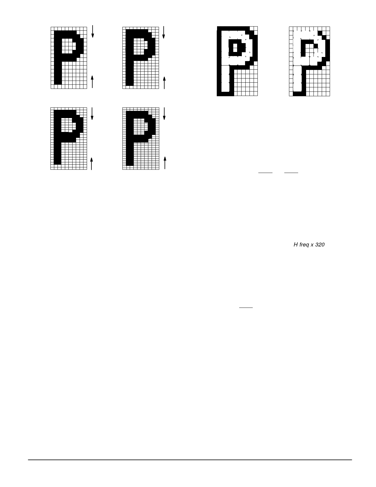
In order to avoid submersion of displayed symbols or char-
acters into a background of comparable colors, a feature of
bordering which encircles all four sides, or shadowing which
encircles only the right and bottom sides of an individual dis-
play character, are provided. Figure 7 shows how a character
is jacketed differently. To make sure that a character is bor-
dered or shadowed correctly, at least one blank dot should
be reserved on each side of the character font.
ÎÎÎÎÎÎÎÎÎ1111119876543211043205 ÏÏÏÏÏÏÏÎÎÎÎÎÎÎÎÎBoÏÏÏÏÏÏÏÎÎÎÎÎÎÎÎÎrderiÏÏÏÏÎÎÎÎÎÎÎÎÎng ÏÏÏÏÎÎÎÎÎÎÎÎÎÎÎÎÎÎÎÎÎÎ
111111ÎÎÎÎÎÎÎÎÎ9876543211043205 ÏÏÏÏÏÏÏÎÎÎÎÎÎÎÎÎShadÏÏÏÏÎÎÎÎÎÎÎÎÎowinÏÏÏÏÎÎÎÎÎÎÎÎÎg ÏÏÏÏÎÎÎÎÎÎÎÎÎ
Figure 7. Character Bordering and Shadowing
Frame Format and Timing
Figure 8 illustrates the positions of all display characters
on the screen relative to the leading edge of horizontal and
vertical flyback signals. The shaded area indicates the area
outside the “safe viewing area” for the display characters.
Notice that there are two components in the equations stated
in Figure 8 for horizontal and vertical delays: fixed delays
from the leading edge of HFLB and VFLB signals, regardless
of the values of HORD and VERTD (47 dots + phase detec-
tion pulse width) and one H scan line for horizontal and verti-
cal delays, respectively; and variable delays determined by
the values of HORD and VERTD. Refer to Frame Control
Registers Coln 9 and 10 for the definitions of VERTD and
HORD.
Phase detection pulse width is a function of the external
charge–up resistor, which is the 330 kΩ resistor in a series
with 2 kΩ to VCO pin in the Application Diagram. Dot fre-
quency is determined by the equation H freq x 320. For ex-
ample, dot frequency is 10.24 MHz if H freq is 32 kHz.
Hence, a dot equals 1/10.24 µs.
When double character width is selected for a row, only the
even–numbered characters will be displayed, as shown in
Row 2. Notice that the total number of horizontal scan lines in
the display frame is variable, depending on the chosen char-
acter height of each row. Care should be taken while config-
uring each row character height so that the last horizontal
scan line in the display frame always comes out before the
leading edge of VFLB of the next frame, to avoid wrapping
display characters of the last few rows in the current frame
into the next frame. The number of display dots in a horizon-
tal scan line is always fixed at 240, regardless of row charac-
ter width.
MOTOROLA
MC141540
7
Share Link: 