MC13081XB View Datasheet(PDF) - Motorola => Freescale
Part Name
Description
Manufacturer
MC13081XB
Motorola => Freescale

MC13081XB Datasheet PDF : 20 Pages
| |||
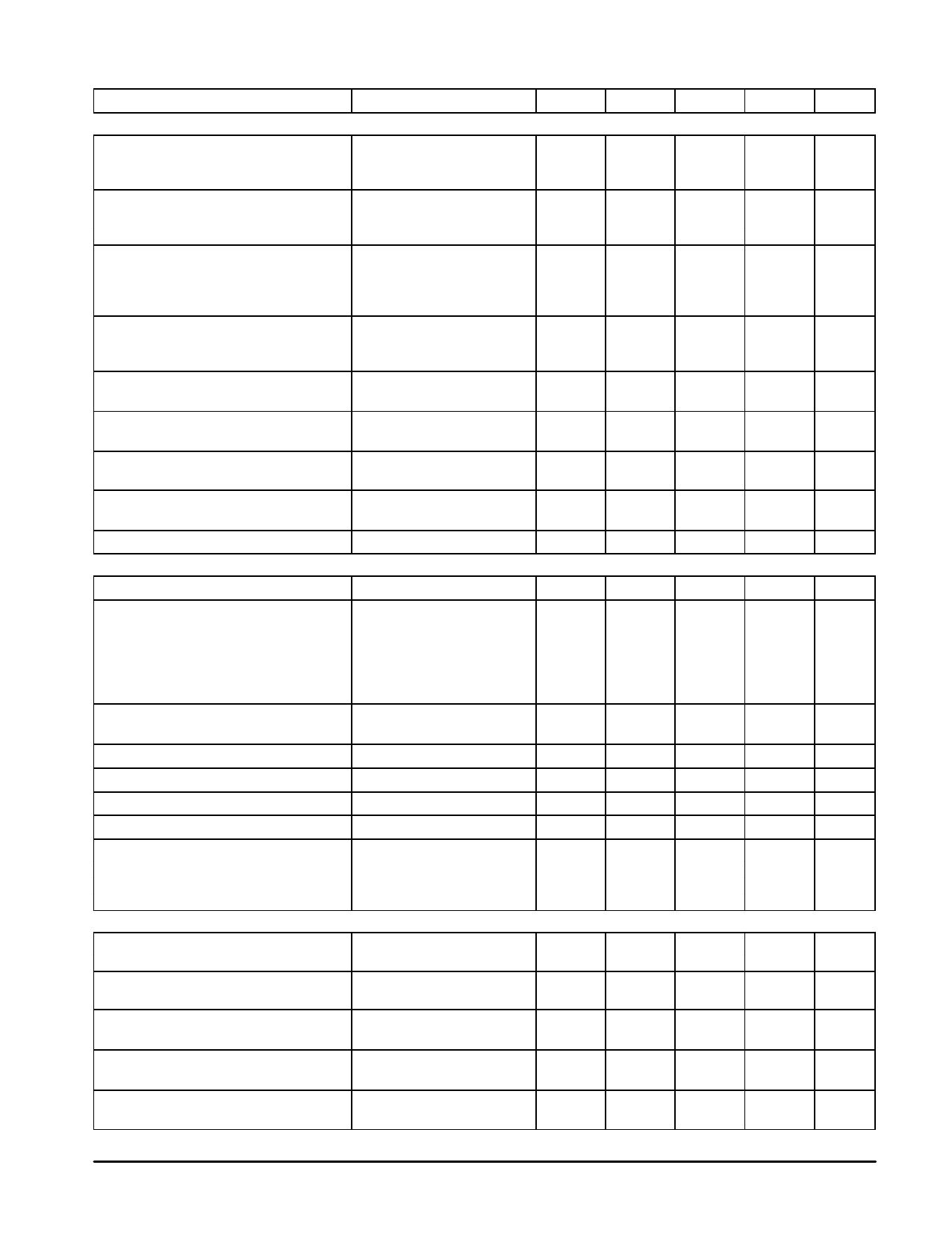
MC13081X
ELECTRICAL CHARACTERISTICS (continued) (TA = 25°C, VCC = 8.0 Vdc)
Characteristic
Condition
Pin
Min
Typ
Max
Unit
HORIZONTAL DRIVE
Horizontal Position Adjust
Range
Input Impedance
0 < V55 < 5.0 V,
55
FH = 30 k – 56 kHz
See Application Section 7
Horizontal Drive Width Adjust
Range
Input Impedance
FH = 35 kHz, 0 < V44 < 5.0 V
44
Horizontal Flyback
Threshold
Input Amplitude
Input Impedance
See Application Section 4
46
Input Signal Should Not Fall
Below –0.2 V
Horizontal Drive
Output Low
Output High
43
Isink = 40 mA
V43 = VCC
Time Delay from Flyback to Video Output
See Application Section 7
–
Blanking
–
10
–
%
–
31
–
kΩ
2:1
–
1:2
%
–
30
–
kΩ
–
0.7
–
V
0
–
8.0
V
–
10
–
kΩ
0
–
0.3
Vdc
–
–
100
µA
–
250
–
ns
Time Delay from Blanking to Video Output
See Application Section 7
–
Blanking
–
400
–
ns
X–Ray Shutdown
Activate Voltage
Temperature Coefficient of X–Ray
Threshold Voltage
See Application Section 11
41
–
41
0.4
0.58
0.7
Vdc
–
–2.3
–
mV/°C
Horizontal Jitter
30 kHz < FH < 56 kHz
43
–
3.0
–
ns
VERTICAL PROCESSING
Vertical Ramp Frequency
–
48
45
–
100
Hz
Vertical Ramp
Amplitude
Minimum Peak
Maximum Peak
Output Current
Non–Linearity
Vertical Ramp Free Running Temperature
Drift
FV = 50 Hz,
R12 + VR4 = 820 kΩ
R10 + VR3 =120 kΩ,
C6 = C7 = 1.0 µF
FV = 50 Hz
48
–
3.0
–
Vpp
–
1.9
–
V
–
3.4
–
V
–
2.0
–
mA
–
0.45
1.0
%
48
–
0.01
–
Hz/°C
Vertical Ramp Free Running Drift with VCC
Vertical Ramp Discharge Rate (Retrace)
FV = 50 Hz
FV = 50 Hz
48
–
0.5
–
Hz/V
48
–
9.5
–
V/ms
Vertical Sync Detector Output/+VE Sync
53
–
0
–
Vdc
Vertical Sync Detector Output/–VE Sync
53
–
3.6
–
Vdc
Vertical Sync Input
Input Impedance
Input Level – Low
Input Level – High
–
4
–
22
–
kΩ
0
–
0.8
Vdc
2.4
–
5.0
Vdc
VIDEO AMPLIFIERS
Input Impedance
Internal DC Bias Voltage
–
23, 25,27
100
–
–
kΩ
–
2.4
–
Vdc
Output Signal Amplitude
Voltage Gain
Vin = 0.7 Vpp, V18 = 5.0 V 39, 34, 31
–
3.6
–
Vpp
V20 = V24 = V26 = 0 V
–
5.1
–
V/V
Contrast Control
V18 = 0 to 5.0 V;
V20, 24, 26 = 0 V
18
–
20
–
dB
Subcontrast Control
V20, 24, 26 = 2.0 to 0 V;
20, 24, 26 1:2.5
–
V18 = 5.0 V
–
–
Brightness Control
V19 = 0 to 5.0 V, Measure
19
Pin 39, 34, 31 DC Level
–
±0.5
–
Vdc
MOTOROLA ANALOG IC DEVICE DATA
5
Share Link: