M2716F1 View Datasheet(PDF) - STMicroelectronics
Part Name
Description
Manufacturer
M2716F1 Datasheet PDF : 9 Pages
| |||
M2716
DEVICE OPERATION (cont’d)
pulse width between 45ms and 55ms. Multiple
pulses are not needed but will not cause device
damage. No pins should be left open. A high level
(VIH or higher) must not be maintained longer than
tPHPL (max) on the program pin during program-
ming. M2716’s may be programmed in parallel in
this mode.
Program Verify Mode. The programming of the
M2716 may be verified either one byte at a time
during the programming (as shown in Figure 6) or
by reading all of the bytes out at the end of the
programming sequence. This can be done with
VPP = 25V or 5V in either case. VPP must be at 5V
for all operating modes and can be maintained at
25V for all programming modes.
Program Inhibit Mode. The program inhibit mode
allows several M2716’s to be programmed simul-
taneously with different data for each one by con-
trolling which ones receive the program pulse. All
similar inputs of the M2716 may be paralleled.
Pulsing the program pin (from VIL to VIH) will pro-
gram a unit while inhibiting the program pulse to a
unit will keep it from being programmed and keep-
ing G = VIH will put its outputs in the Hi-Z state.
ERASURE OPERATION
The M2716 is erased by exposure to high intensity
ultraviolet light through the transparent window.
This exposure discharges the floating gate to its
initial state through induced photo current. It is
recommended that the M2716 be kept out of direct
sunlight. The UV content of sunlight may cause
a partial erasure of some bits in a relatively short
period of time.
An ultraviolet source of 2537 Å yielding a total
integrated dosage of 15 watt-seconds/cm2 power
rating is used. The M2716 to be erased should be
placed 1 inch away from the lamp and no filters
should be used.
An erasure system should be calibrated peri-
odically. The erasure time is increased by the
square of the distance (if the distance is doubled
the erasure time goes up by a factor of 4). Lamps
lose intensity as they age, it is therefore important
to periodically check that the UV system is in good
order.
This will ensure that the EPROMs are being com-
pletely erased. Incomplete erasure will cause
symptoms that can be misleading. Programmers,
components, and system designs have been erro-
neously suspected when incomplete erasure was
the basic problem.
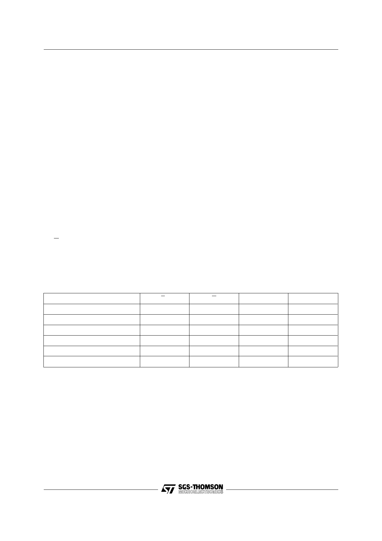
Table 3. Operating Modes
Mode
Read
Program
Verify
Program Inhibit
Deselect
Standby
Note: X = VIH or VIL.
EP
VIL
VIH Pulse
VIL
VIL
X
VIH
G
VPP
Q0 - Q7
VIL
VCC
Data Out
VIH
VPP
Data In
VIL
VPP or VCC
Data Out
VIH
VPP
Hi-Z
VIH
VCC
Hi-Z
X
VCC
Hi-Z
3/9
Share Link: 