M27V400 View Datasheet(PDF) - STMicroelectronics
Part Name
Description
Manufacturer
M27V400 Datasheet PDF : 14 Pages
| |||
M27V400
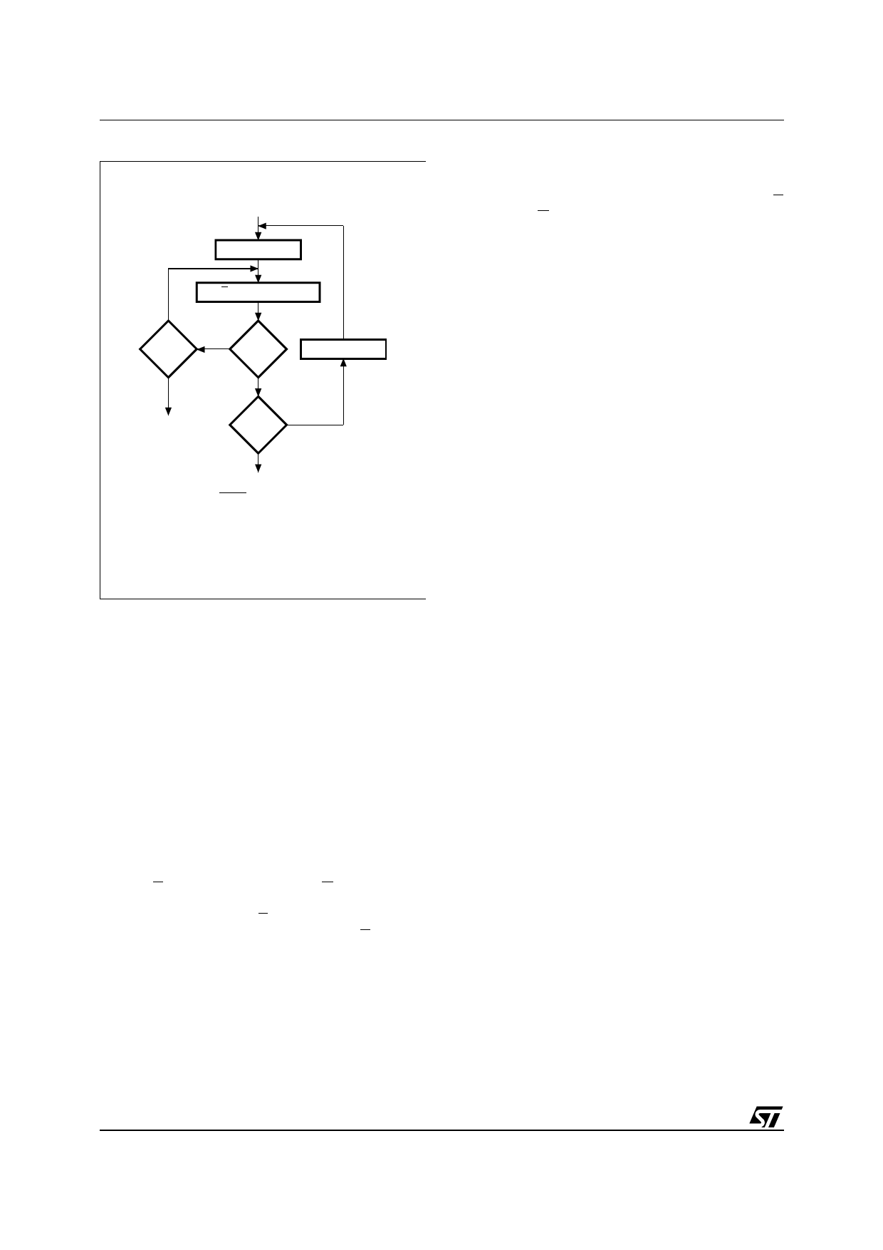
Figure 9. Programming Flowchart
VCC = 6.25V, VPP = 12.5V
n=0
NO
++n
= 25
YES
E = 50µs Pulse
NO
VERIFY
YES
++ Addr
FAIL
Last NO
Addr
YES
CHECK ALL WORDS
BYTEVPP =VIH
1st: VCC = 6V
2nd: VCC = 3V
AI03075
PRESTO III Programming Algorithm
The PRESTO III Programming Algorithm allows
the whole array to be programed with a guaran-
teed margin in a typical time of 13 seconds. Pro-
gramming with PRESTO III consists of applying a
sequence of 50µs program pulses to each word
until a correct verify occurs (see Figure 9). During
programing and verify operation a MARGIN
MODE circuit is automatically activated to guaran-
tee that each cell is programed with enough mar-
gin. No overpromise pulse is applied since the
verify in MARGIN MODE provides the necessary
margin to each programmed cell.
Program Inhibit
Programming of multiple M27V400s in parallel
with different data is also easily accomplished. Ex-
cept for E, all like inputs including G of the parallel
M27V400 may be common. A TTL low level pulse
applied to a M27V400's E input and VPP at 12.5V,
will program that M27V400. A high level E input in-
hibits the other M27V400s from being pro-
grammed.
Program Verify
A verify (read) should be performed on the pro-
grammed bits to determine that they were correct-
ly programmed. The verify is accomplished with E
at VIH and G at VIL, VPP at 12.5V and VCC at
6.25V.
Electronic Signature
The Electronic Signature (ES) mode allows the
reading out of a binary code from an EPROM that
will identify its manufacturer and type. This mode
is intended for use by programming equipment to
automatically match the device to be programmed
with its corresponding programming algorithm.
The ES mode is functional in the 25°C ± 5°C am-
bient temperature range that is required when pro-
gramming the M27V400. To activate the ES mode,
the programming equipment must force 11.5V to
12.5V on address line A9 of the M27V400, with
VPP = VCC = 5V. Two identifier bytes may then be
sequenced from the device outputs by toggling ad-
dress line A0 from VIL to VIH. All other address
lines must be held at VIL during Electronic Signa-
ture mode.
Byte 0 (A0 = VIL) represents the manufacturer
code and byte 1 (A0 = VIH) the device identifier
code. For the STMicroelectronics M27V400, these
two identifier bytes are given in Table 4 and can be
read-out on outputs Q7 to Q0.
ERASURE OPERATION (applies to UV EPROM)
The erasure characteristics of the M27V400 is
such that erasure begins when the cells are ex-
posed to light with wavelengths shorter than ap-
proximately 4000 Å. It should be noted that
sunlight and some type of fluorescent lamps have
wavelengths in the 3000-4000 Å range. Research
shows that constant exposure to room level fluo-
rescent lighting could erase a typical M27V400 in
about 3 years, while it would take approximately 1
week to cause erasure when exposed to direct
sunlight. If the M27V400 is to be exposed to these
types of lighting conditions for extended periods of
time, it is suggested that opaque labels be put over
the M27V400 window to prevent unintentional era-
sure. The recommended erasure procedure for
M27V400 is exposure to short wave ultraviolet
light which has a wavelength of 2537 Å. The inte-
grated dose (i.e. UV intensity x exposure time) for
erasure should be a minimum of 30 W-sec/cm2.
The erasure time with this dosage is approximate-
ly 30 to 40 minutes using an ultraviolet lamp with
12000 µW/cm2 power rating. The M27V400
should be placed within 2.5cm (1 inch) of the lamp
tubes during the erasure. Some lamps have a filter
on their tubes which should be removed before
erasure.
10/14
Share Link: 