M27V400 View Datasheet(PDF) - STMicroelectronics
Part Name
Description
Manufacturer
M27V400 Datasheet PDF : 14 Pages
| |||
M27V400
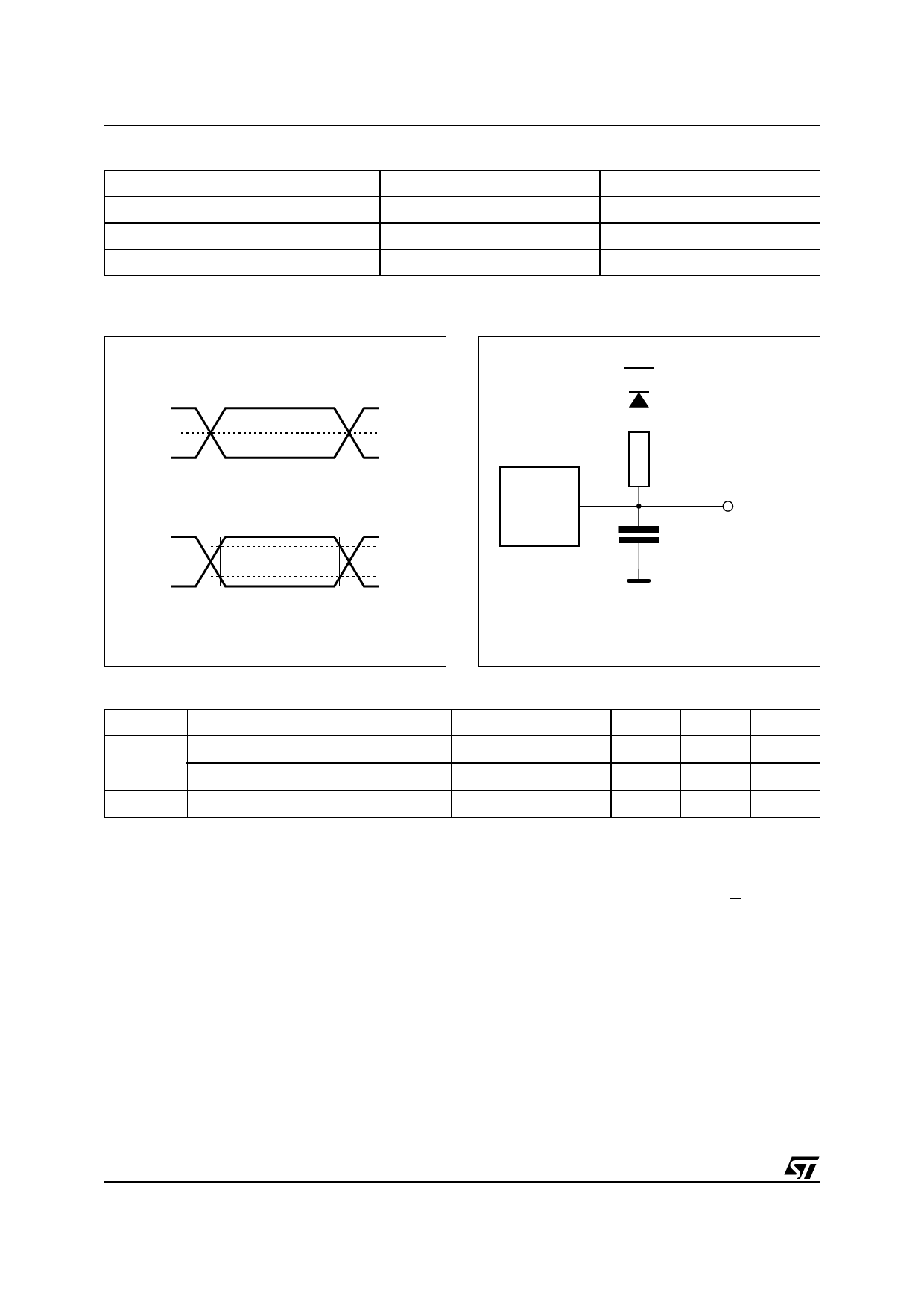
Table 5. AC Measurement Conditions
Input Rise and Fall Times
Input Pulse Voltages
Input and Output Timing Ref. Voltages
High Speed
≤ 10ns
0 to 3V
1.5V
Standard
≤ 20ns
0.4V to 2.4V
0.8V and 2V
Figure 3. Testing Input Output Waveform
High Speed
3V
0V
Standard
2.4V
0.4V
1.5V
2.0V
0.8V
AI01822
Figure 4. AC Testing Load Circuit
1.3V
1N914
DEVICE
UNDER
TEST
3.3kΩ
CL
OUT
CL = 30pF for High Speed
CL = 100pF for Standard
CL includes JIG capacitance
AI01823B
Table 6. Capacitance (1) (TA = 25 °C, f = 1 MHz)
Symbol
Parameter
Input Capacitance (except BYTEVPP)
CIN
Input Capacitance (BYTEVPP)
COUT Output Capacitance
Note: 1. Sampled only, not 100% tested.
Test Condition
VIN = 0V
VIN = 0V
VOUT = 0V
Min
Max
Unit
10
pF
120
pF
12
pF
Two Line Output Control
Because EPROMs are usually used in larger
memory arrays, this product features a 2-line con-
trol function which accommodates the use of mul-
tiple memory connection. The two-line control
function allows:
a. the lowest possible memory power dissipation
b. complete assurance that output bus contention
will not occur.
For the most efficient use of these two control
lines, E should be decoded and used as the prima-
ry device selecting function, while G should be
made a common connection to all devices in the
array and connected to the READ line from the
system control bus. This ensures that all deselect-
ed memory devices are in their low power standby
mode and that the output pins are only active
when data is required from a particular memory
device.
4/14
Share Link: 