M38500E5H-FP Просмотр технического описания (PDF) - MITSUBISHI ELECTRIC
Номер в каталоге
Компоненты Описание
производитель
M38500E5H-FP Datasheet PDF : 86 Pages
| |||
MITSUBISHI MICROCOMPUTERS
3850 Group (Spec. H)
SINGLE-CHIP 8-BIT CMOS MICROCOMPUTER
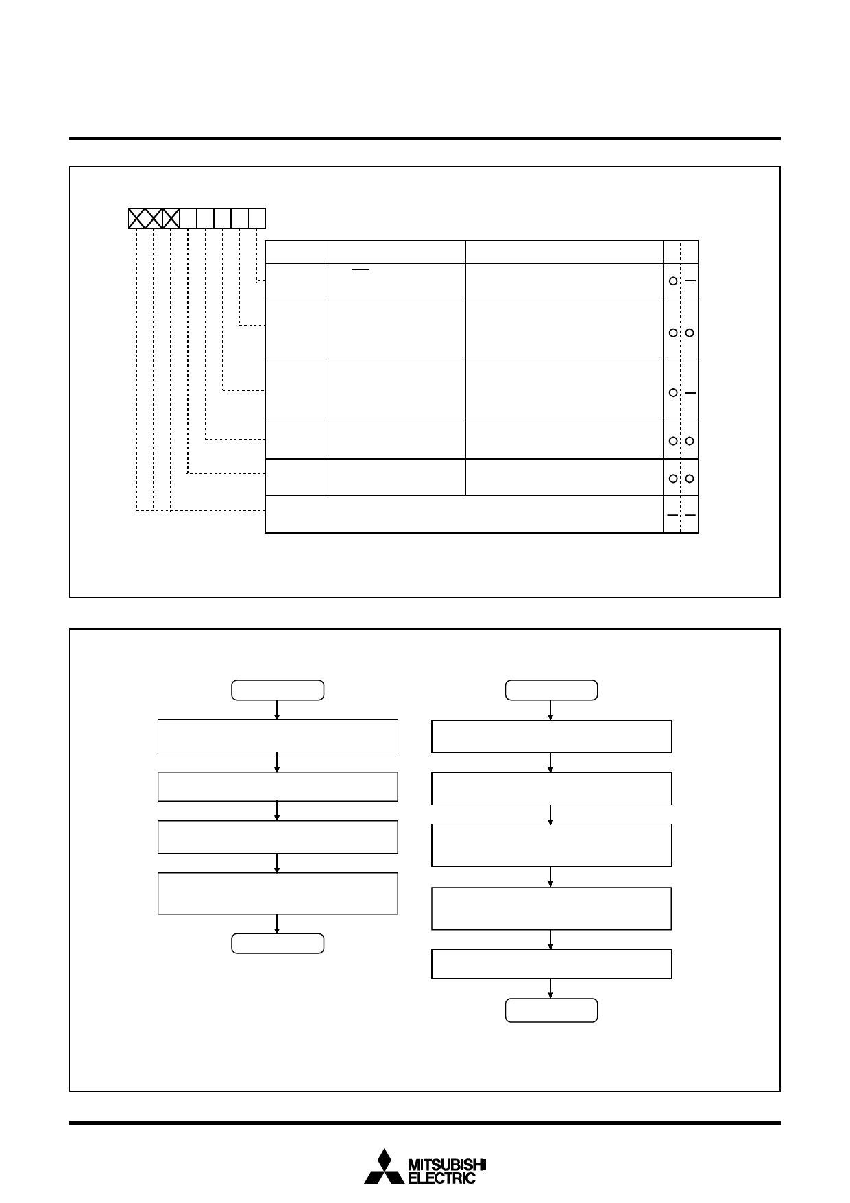
Flash memory control register
b7 b6 b5 b4 b3 b2 b1 b0
Symbol
FMCR
Address
0FFE16
When reset
XXX00001
Bit symbol
Bit name
FMCR0 RY/BY status flag
FMCR1 CPU rewrite mode
select bit (Note 1)
FMCR2 CPU rewrite mode
entry flag
FMCR3 Flash memory reset bit
(Note 2)
FMCR4 User area / Boot area
selection bit
Function
RR WW
0: Busy (being written or erased)
1: Ready
0: Normal mode
(Software commands invalid)
1: CPU rewrite mode
(Software commands acceptable)
0: Normal mode
(Software commands invalid)
1: CPU rewrite mode
(Software commands acceptable)
0: Normal operation
1: Reset
0: User ROM area
1: Boot ROM area
Nothing is assigned.
When write, set “0”. When read, values are indeterminate.
Notes 1: For this bit to be set to “1”, the user needs to write a “0” and then a “1” to it in succession.
2: Effective only when the CPU rewrite mode select bit = 1. Set this bit to “0” subsequently
after setting it to “1” (reset).
Fig. 45 Flash memory control registers
Program in ROM
Start
Single-chip mode, or boot mode
Set CPU mode register (Note 1)
Transfer CPU rewrite mode control
program to internal RAM
Jump to transferred control program in RAM
(Subsequent operations are executed by control
program in this RAM)
*1
Program in RAM
*1
Set CPU rewrite mode select bit to “1” (by
writing “0” and then “1” in succession)
Check the CPU rewrite mode entry flag
Using software command execute erase,
program, or other operation
Execute read array command or reset flash
memory by setting flash memory reset bit (by
writing “1” and then “0” in succession) (Note 2)
Write “0” to CPU rewrite mode select bit
End
Notes 1: Set bit 6, 7 (Main clock division ratio selection bits ) at CPU mode register (003B16).
2: Before exiting the CPU rewrite mode after completing erase or program operation, always be sure to
execute a read array command or reset the flash memory.
Fig. 46 CPU rewrite mode set/reset flowchart
41
Share Link: 