BUT18AF Просмотр технического описания (PDF) - Philips Electronics
Номер в каталоге
Компоненты Описание
производитель
BUT18AF Datasheet PDF : 12 Pages
| |||
Philips Semiconductors
Silicon diffused power transistors
Product specification
BUT18F; BUT18AF
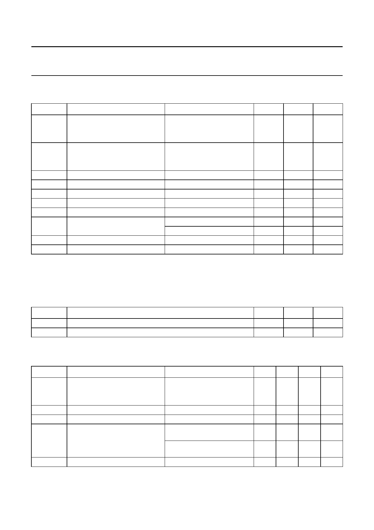
LIMITING VALUES
In accordance with the Absolute Maximum Rating System (IEC 134).
SYMBOL
PARAMETER
CONDITIONS
VCESM
VCEO
ICsat
IC
ICM
IB
IBM
Ptot
Tstg
Tj
collector-emitter peak voltage
BUT18F
BUT18AF
collector-emitter voltage
BUT18F
BUT18AF
collector saturation current
collector current (DC)
collector current (peak value)
base current (DC)
base current (peak value)
total power dissipation
storage temperature
junction temperature
VBE = 0
open base
see Fig.4
see Fig.4
Th ≤ 25 °C; see Fig.2; note 1
Th ≤ 25 °C; see Fig.2; note 2
Notes
1. Without heatsink compound.
2. With heatsink compound.
MIN.
MAX.
UNIT
−
850
V
−
1 000
V
−
400
V
−
450
V
−
4
A
−
6
A
−
12
A
−
3
A
−
6
A
−
20
W
−
33
W
−65
+150
°C
−
150
°C
ISOLATION CHARACTERISTICS
SYMBOL
VisolM
Cisol
PARAMETER
isolation voltage from all terminals to external heatsink (peak value)
isolation capacitance from collector to external heatsink
TYP.
−
12
MAX.
1 500
−
UNIT
V
pF
CHARACTERISTICS
Tj = 25 °C unless otherwise specified.
SYMBOL
PARAMETER
CONDITIONS
MIN. TYP. MAX. UNIT
VCEOsust
VCEsat
VBEsat
ICES
IEBO
collector-emitter sustaining voltage IC = 100 mA; IBoff = 0;
BUT18F
L = 25 mH; see Figs 3 and 6
400 −
BUT18AF
450 −
collector-emitter saturation voltage IC = 4 A; IB = 800 mA; see Fig.7 −
−
base-emitter saturation voltage
IC = 4 A; IB = 800 mA; see Fig.8 −
−
collector-emitter cut-off current
VCE = VCESMmax; VBE = 0;
note 1
−
−
emitter-base cut-off current
VCE = VCESMmax; VBE = 0;
Tj = 125 °C; note 1
VEB = 9 V; IC = 0
−
−
−
−
−
V
−
V
1.5 V
1.3 V
1
mA
2
mA
10
mA
1999 Jun 11
3
Share Link: 