M56755AFP Просмотр технического описания (PDF) - MITSUBISHI ELECTRIC
Номер в каталоге
Компоненты Описание
производитель
M56755AFP Datasheet PDF : 10 Pages
| |||
MITSUBISHI <CONTROL / DRIVER IC>
M56755AFP
SPINDLE MOTOR DRIVER
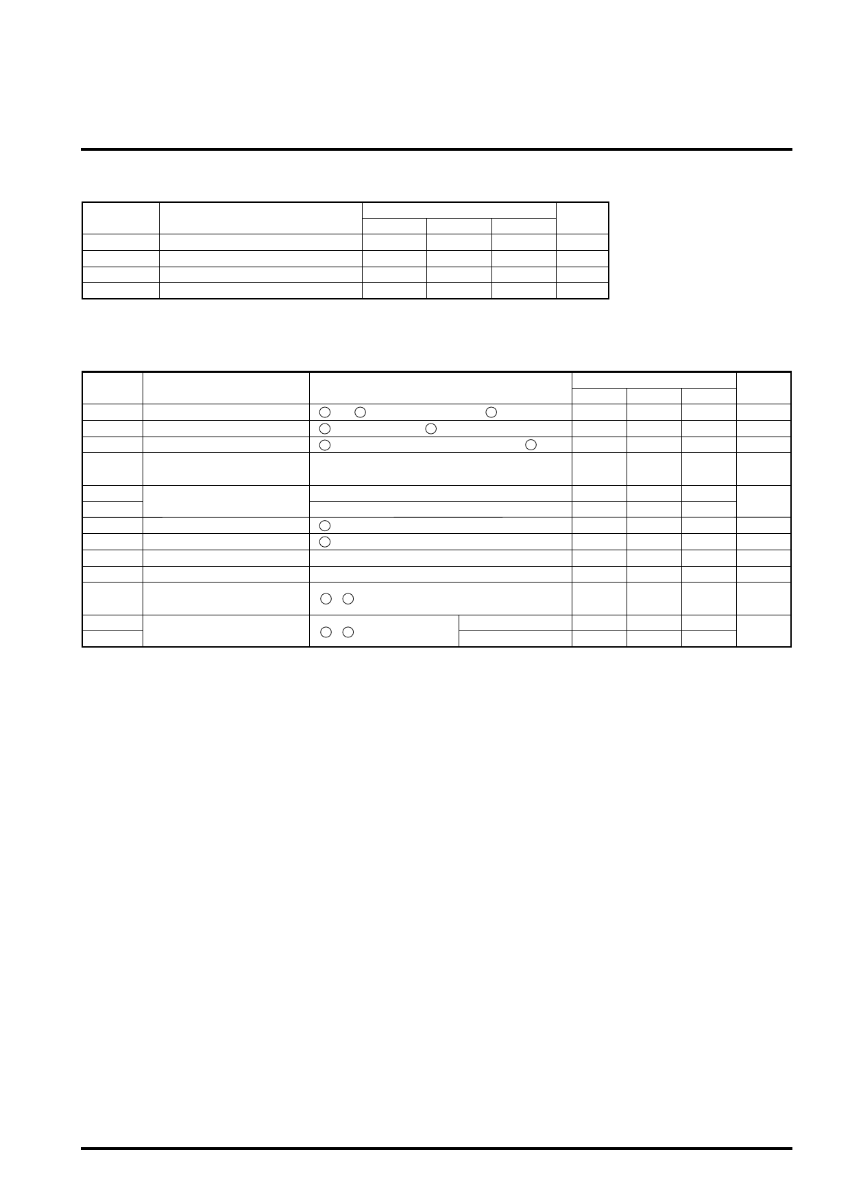
RECOMMENDED OPERATING CONDITIONS
Symbol
Parameter
Min.
VCC1
5V Power supply
4.5
VCC2
12V Power supply
4.5
VM
Motor Power supply
4.5
Io
Output drive current
—
Limits
Typ.
5.0
12.0
12.0
—
Max.
5.5
13.2
13.2
700
Units
V
V
V
mA
ELECTRICAL CHARACTERISTICS (VCC = 5V, VCC2 = 12V ,VM = 12V, Ta = 25°C unless otherwise noted.)
Symbol
Parameter
Conditions
Min.
ICC1
Sleep Mode Supply current - 1 13 and 14 pin total Input Current [ 1 pin lo or open] —
ICC2
Sleep Mode Supply current - 2 17 pin Input Current [ 1 pin lo or open]
—
ICC3
Supply current - 3
17 pin Input Current (EC = ECR = 2.5V) [ 1 pin Hi] —
Vsat
Saturation voltage
Top and Bottom saturation voltage
Load current 500mA
—
ECdead-
ECdead+ Control voltage dead zone
EC < ECR
EC > ECR
-40
0
ECR
Reference voltage Input range 16 pin Input voltage range [3.3V DSP available]
0.5
EC
Control voltage Input range
15 pin Input voltage range [3.3V DSP available]
0.5
Gio
Control gain
Io = Gio / Rsense [A/V]
0.25
Vlim
Control limit
Ilim = Vlim / Rsense [A]
0.27
VH com
Hall sensor amp common
mode input range
19 – 24 pins input range
1.2
VHmin1 Hall sensor amp.
VHmin2 input signal revel
MODE4 = open
50
19 – 24 pins input signal
MODE4 = GND
35
Limits
Typ.
0
—
—
1.2
-21
+21
1.65
1.65
0.3
0.3
—
—
—
Max.
100
500
6.0
1.9
0
+40
4.0
4.0
0.35
0.33
4.5
—
—
Units
µA
µA
mA
V
mV
V
V
V/V
V
V
mVp-p
Share Link: 