LA7837 Просмотр технического описания (PDF) - SANYO -> Panasonic
Номер в каталоге
Компоненты Описание
производитель
LA7837 Datasheet PDF : 9 Pages
| |||
LA7837, 7838
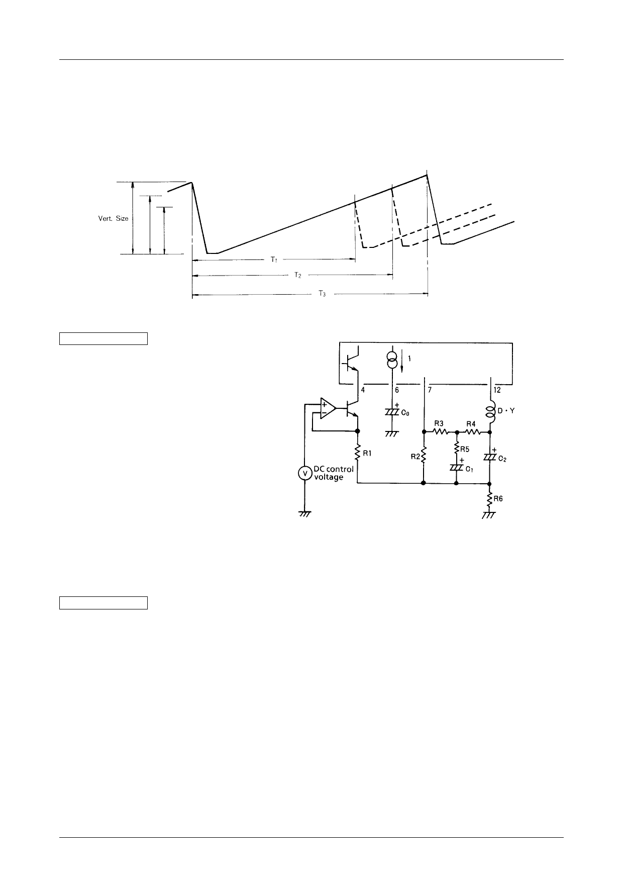
LA7837, 7838 application in a multi-sync system
The LA7837, 7838 can also be used in a vertical frequency multi-sync system.
The LA7837, 7838 do not have an on-chip vertical oscillation circuit, so they operate merely by impressing a trigger
pulse (e.g. 40 to 80Hz) on pin 2.
However, there are two problems with using the LA7837, 7838 as are in a multi-sync system.
One is vertical amplitude. When the trigger pulse changes between 40 to 80Hz, the vertical frequency will rise and
amplitude size decreases (because pin 6 cycle (T1, T2) in the diagram below becomes shorter).
Countermeasure 1
In order to stabilize vertical size change, an
operational amplifier is used to change the
circuit to one which controls pin 4 vertical
size control current.
Voltage which corresponds to vertical fre-
quency changes is applied to the operational
amplifier to stabilize vertical size.
Fig. 8
The other problem is that vertical linearity chages when used at multi-frequency (e.g. 40 to 80Hz).
The reason for this is that R5 and C1 time constants are used for linearity correction (Fig.9), so even though the value
is optimum for a certain frequency, it is not for others.
Countermeasure 2
As shown in Fig.10, good linearity can be obtained by setting frequency ranges of use for R5 and C1 time constants for
vertical linearity correction, and switching them.
For example :
40 to 60Hz Switch A
60 to 80Hz Switch B
For switch A, R5 and C1 are set so that vertical linearity response is optimum for fv≈50Hz.
Next, for switch B, R5’ and C1’ are set for optimum value at fv≈70Hz.
By dividing the vertical trigger pulse range (e.g.40 to 80Hz) and performing linearity correction in this way, linearity
distortion can be kept below about 3%.
No.3313–8/9
Share Link: 