74LVQ161(2004) Просмотр технического описания (PDF) - STMicroelectronics
Номер в каталоге
Компоненты Описание
производитель
74LVQ161 Datasheet PDF : 14 Pages
| |||
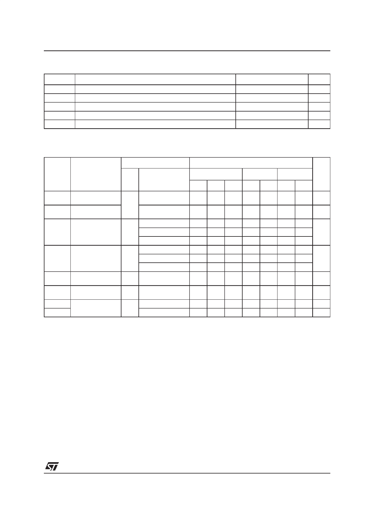
74LVQ161
Table 8: AC Electrical Characteristics (CL = 50 pF, RL = 500 Ω, Input tr = tf = 3ns)
Test Condition
Symbol
Parameter
VCC
(V)
tPLH tPHL Propagation Delay
Time CK to Q
tPLH tPHL Propagation Delay
Time CK to CARRY
OUT
tPLH tPHL Propagation Delay
Time TE to CARRY
OUT
tPHL Propagation Delay
Time CLR to Q
tPHL
tW(L)
Propagation Delay
Time CLR to
CARRY OUT
CLR Pulse Width,
LOW (LOAD)
tW
ts
th
ts
th
ts
th
tREM
CLOCK Pulse
Width, HIGH or
LOW
Setup Time HIGH
or LOW
(INPUT to CLOCK)
Hold Time HIGH or
LOW
(INPUT to CLOCK)
Setup Time HIGH
or LOW (LOAD to
CLOCK)
Hold Time HIGH or
LOW (LOAD to
CLOCK)
Setup Time HIGH
or LOW (PE or TE
to CLOCK)
Hold Time HIGH or
LOW (PE or TE
to CLOCK)
Recovery Time
CLR to CK
fMAX Maximum Clock
Frequency
tOSLH
tOSHL
Output To Output
Skew Time
(note1, 2)
2.7
3.3(*)
2.7
3.3(*)
2.7
3.3(*)
2.7
3.3(*)
2.7
3.3(*)
2.7
3.3(*)
2.7
3.3(*)
2.7
3.3(*)
2.7
3.3(*)
2.7
3.3(*)
2.7
3.3(*)
2.7
3.3(*)
2.7
3.3(*)
2.7
3.3(*)
2.7
3.3(*)
2.7
3.3(*)
Value
TA = 25°C
-40 to 85°C -55 to 125°C Unit
Min. Typ. Max. Min. Max. Min. Max.
8.0 13.0
6.8 9.5
15.0
11.0
17.0
ns
12.5
9.1 14.0
7.5 10.5
16.0
12.0
18.5
ns
14.0
5.6 10.0
11.5
13.0
4.7 8.0
ns
9.5
10.5
8.0 12.0
6.1 9.5
8.0 14.0
6.7 10.5
15.0
11.0
16.0
12.0
17.0
ns
12.5
18.5
ns
14.0
4.0 1.9
4.0
4.0
ns
3.0 1.9
3.0
3.0
4.0 1.9
4.0
4.0
ns
3.0 1.9
3.0
3.0
5.0 2.5
5.0
5.0
ns
4.0 2.1
4.0
4.0
1 -1.3
1
1
ns
0.5 -1.0
0.5
0.5
3.0 1.5
3.0
3.0
ns
2.5 1.2
2.5
2.5
1 -0.6
1
1
ns
0.5 -0.5
0.5
0.5
7.0 3.4
7.0
7.0
ns
6.0 3.0
6.0
6.0
0 -2.6
0
0 -2.2
0
0
ns
0
1 -0.8
1
1
ns
0.5 -0.6
0.5
0.5
100 150
80
120 180
100
60
MHz
80
0.5 1.0
1.0
1.0
0.5 1.0
1.0
1.0 ns
1) Skew is defined as the absolute value of the difference between the actual propagation delay for any two outputs of the same device switch-
ing in the same direction, either HIGH or LOW (tOSLH = |tPLHm - tPLHn|, tOSHL = |tPHLm - tPHLn|)
2) Parameter guaranteed by design
(*) Voltage range is 3.3V ± 0.3V
5/14
Share Link: 