AT40K05AL Просмотр технического описания (PDF) - Atmel Corporation
Номер в каталоге
Компоненты Описание
производитель
AT40K05AL Datasheet PDF : 51 Pages
| |||
3. The Busing Network
Figure 3-1 depicts one of five identical busing planes. Each plane has three bus resources: a local-bus resource
(the middle bus) and two express-bus (both sides) resources. Bus resources are connected via repeaters. Each
repeater has connections to two adjacent local-bus segments and two express-bus segments. Each local-bus
segment spans four cells and connects to consecutive repeaters. Each express-bus segment spans eight cells and
“leapfrogs” or bypasses a repeater. Repeaters regenerate signals and can connect any bus to any other bus (all
pathways are legal) on the same plane. Although not shown, a local bus can bypass a repeater via a
programmable pass gate allowing long on-chip tri-state buses to be created. Local/Local turns are implemented
through pass gates in the cell-bus interface. Express/Express turns are implemented through separate pass gates
distributed throughout the array.
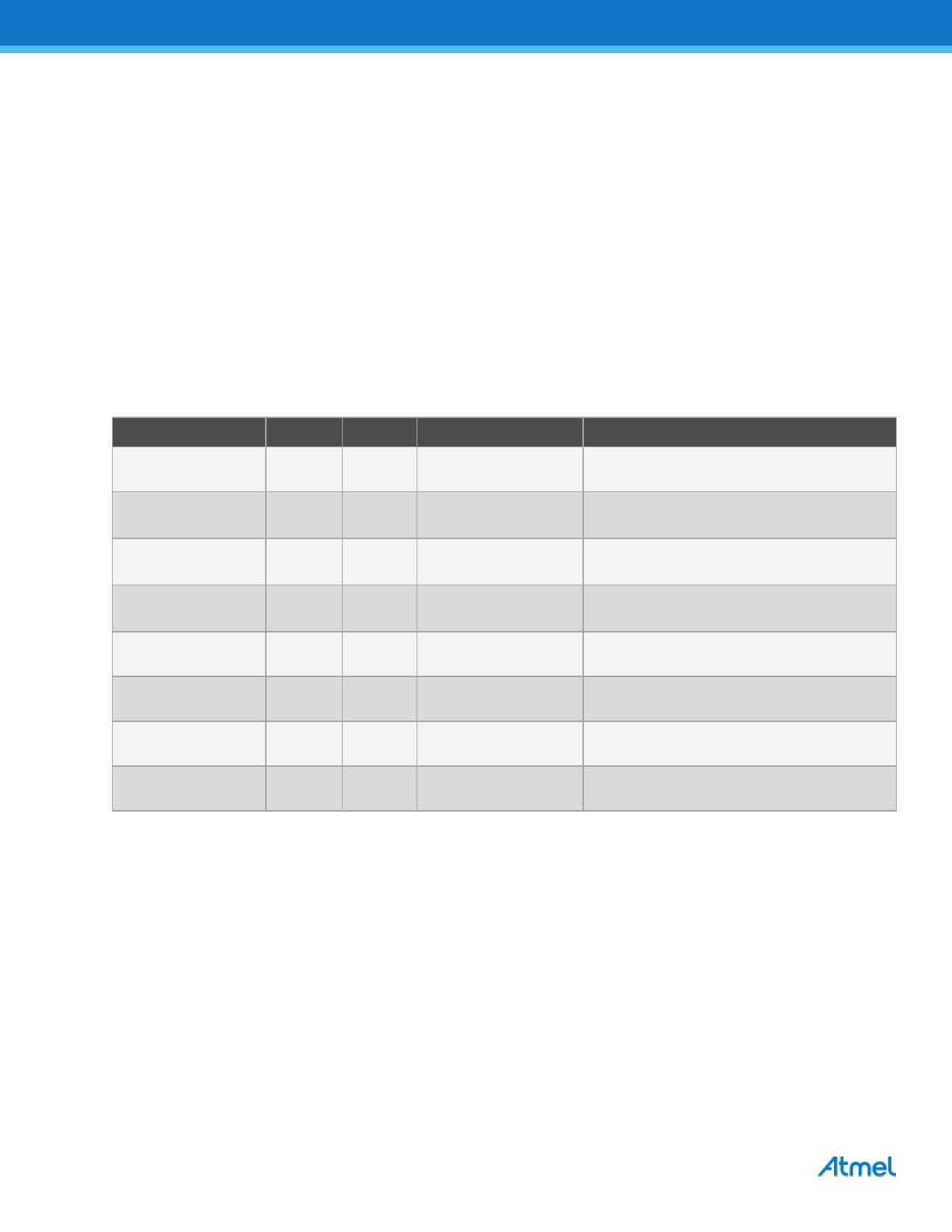
Some of the bus resources on the AT40KAL are used as a dual-function resources. Table 3-1 shows which buses
are used in a dual-function mode and which bus plane is used. The AT40KAL software tools are designed to
accommodate dual-function buses in an efficient manner.
Table 3-1. Dual-function Buses
Function
Type Plane(s)
Direction
Comments
Cell Output Enable
Local
5
Horizontal and Vertical
RAM Output Enable Express
2
RAM Write Enable
Express
1
RAM Address
Express 1 – 5
Vertical
Vertical
Vertical
Bus full length at array edge.
Bus in first column to left of RAM block.
Bus full length at array edge.
Bus in first column to left of RAM block.
Buses full length at array edge.
Buses in second column to left of RAM block.
RAM Data In
Local
1
Horizontal
Data In connects to local bus plane 1.
RAM Data Out
Local
2
Horizontal
Data out connects to local bus plane 2.
Clocking
Express
4
Vertical
Bus half length at array edge.
Set/Reset
Express
5
Vertical
Bus half length at array edge.
6
AT40KAL Series FPGA [Datasheet]
Atmel-2818G-FPGA-AT40KAL-Series-Datasheet_092013
Share Link: 