HA17384HRP Просмотр технического описания (PDF) - Hitachi -> Renesas Electronics
Номер в каталоге
Компоненты Описание
производитель
HA17384HRP
Hitachi -> Renesas Electronics
HA17384HRP Datasheet PDF : 31 Pages
| |||
HA17384SPS/SRP, HA17384HPS/HRP, HA17385HPS/HRP
Electrical Characteristics (cont)
Current Sensing Part
Item
Symbol Min Typ Max Unit Test Condition
Note
Voltage gain
AVCS
2.85 3.00 3.15 V/V VFB = 0 V
1
Maximum sensing voltage VthCS
0.9 1.0 1.1 V
Power supply voltage
PSRR
—
70
—
dB 12 V ≤ VIN ≤ 25 V
2
rejection ratio
Input bias current
Current sensing
response time
I BCS
—
–2
–10 µA VCS = 2 V
tpd
50 100 150 ns Time from when VCS
3
becomes 2 V to when
output becomes “L” (2 V)
Notes: 1. The gain this case is the ratio of error amplifier output change to the current-sensing threshold
voltage change.
2. Reference value for design.
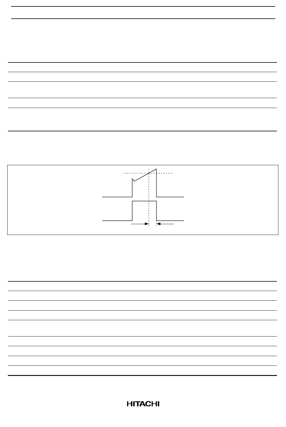
3. Current sensing response time tpd is definded a shown in the figure 1.
Vth
VCS
VOUT
(PWM)
tpd
Figure 1 Definition of Current Sensing Response Time tpd
PWM Output Part
Item
Symbol
Output low voltage 1
Output low voltage 2
Output high voltage 1
Output high voltage 2
Output low voltage at
standby mode
VOL1
VOL2
VOH1
VOH2
VOL STB
Rise time
Fall time
Maximum ON duty
tr
tf
Du max
Minimum ON duty
Du min
Notes: 1. Pulse application test
Min
—
—
13.0
12.0
—
—
—
94
—
Typ
0.7
1.5
13.5
13.3
0.8
80
70
96
—
Max
1.5
2.2
—
—
1.1
150
130
100
0
Unit
V
V
V
V
V
ns
ns
%
%
Test Condition
losink = 20 mA
losink = 200 mA
losource = –20 mA
losource = –200 mA
VIN = 5 V,
losink = 1 mA
CL = 1000 pF
CL = 1000 pF
Note
1
1
9
Share Link: 