IP101A Просмотр технического описания (PDF) - Unspecified
Номер в каталоге
Компоненты Описание
производитель
IP101A Datasheet PDF : 36 Pages
| |||
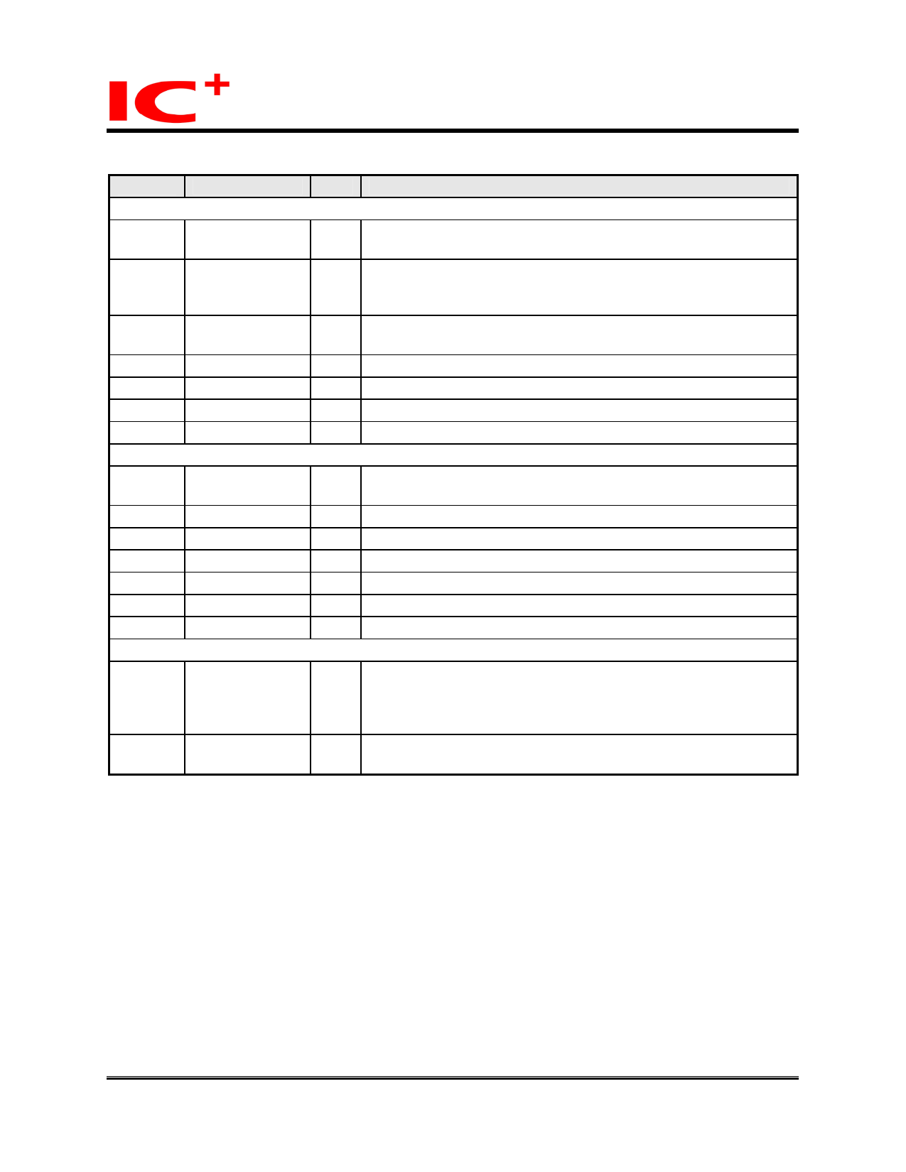
Pin Descriptions (continued)
IP101A LF
Data Sheet
Pin no.
Label
Type
Description
RMII (Reduced MII)
7
REF_CLK
I Reference Clock: This pin is an input pin operates as 50MHz
reference clock (REF_CLK) in RMII mode.
16 C50M_O
O Reference Clock out: This pin could be configured as 50MHz
clock output in RMII mode. With 25MHz crystal/oscillator, IP101A
LF could generate 50MHz output for RMII mode.
2
TX_EN
I Transmit Enable: For MAC to indicate transmit operation
(PD)
5,6 TXD[1:0]
I Transmit two-bit Data
24 RX_ER
I/O Receive Error
22 CRS_DV
O Carrier Sense and Receive Data Valid
20, 21 RXD[1:0]
O Received two-bit Data
SNI (Serial Network Interface): 10Mbps only
2
TX_EN
I Transmit Enable: Indicate transmit operation to MAC
(PD)
7
TX_CLK
O Transmit Clock: 10MHz, clock generated by PHY
6
TXD0
I Transmit Serial Data
16 RX_CLK
O Receive Clock: 10MHz, clock recovery from received data
21 RXD0
O Received Serial Data
1
COL
O Collision Detect
23 CRS
O Carrier Sense
Cable Transmission Interface
34 MDI_TP
33 MDI_TN
I/O Transmit Output Pair: Differential pair shared by 100Base-TX
I/O and 10Base-T modes. When configured as 100Base-TX, output
is an MLT-3 encoded waveform. When configured as 10Base-T,
the output is Manchester code.
31 MDI_RP
30 MDI_RN
I/O Receive Input Pair: Differential pair shared by 100Base-TX and
I/O 10Base-T modes.
8/36
Copyright © 2004, IC Plus Corp.
Oct 22, 2007
IP101A LF-DS-R12
Share Link: 