IRPLDIM2E Просмотр технического описания (PDF) - International Rectifier
Номер в каталоге
Компоненты Описание
производитель
IRPLDIM2E Datasheet PDF : 13 Pages
| |||
IRPLDIM2E
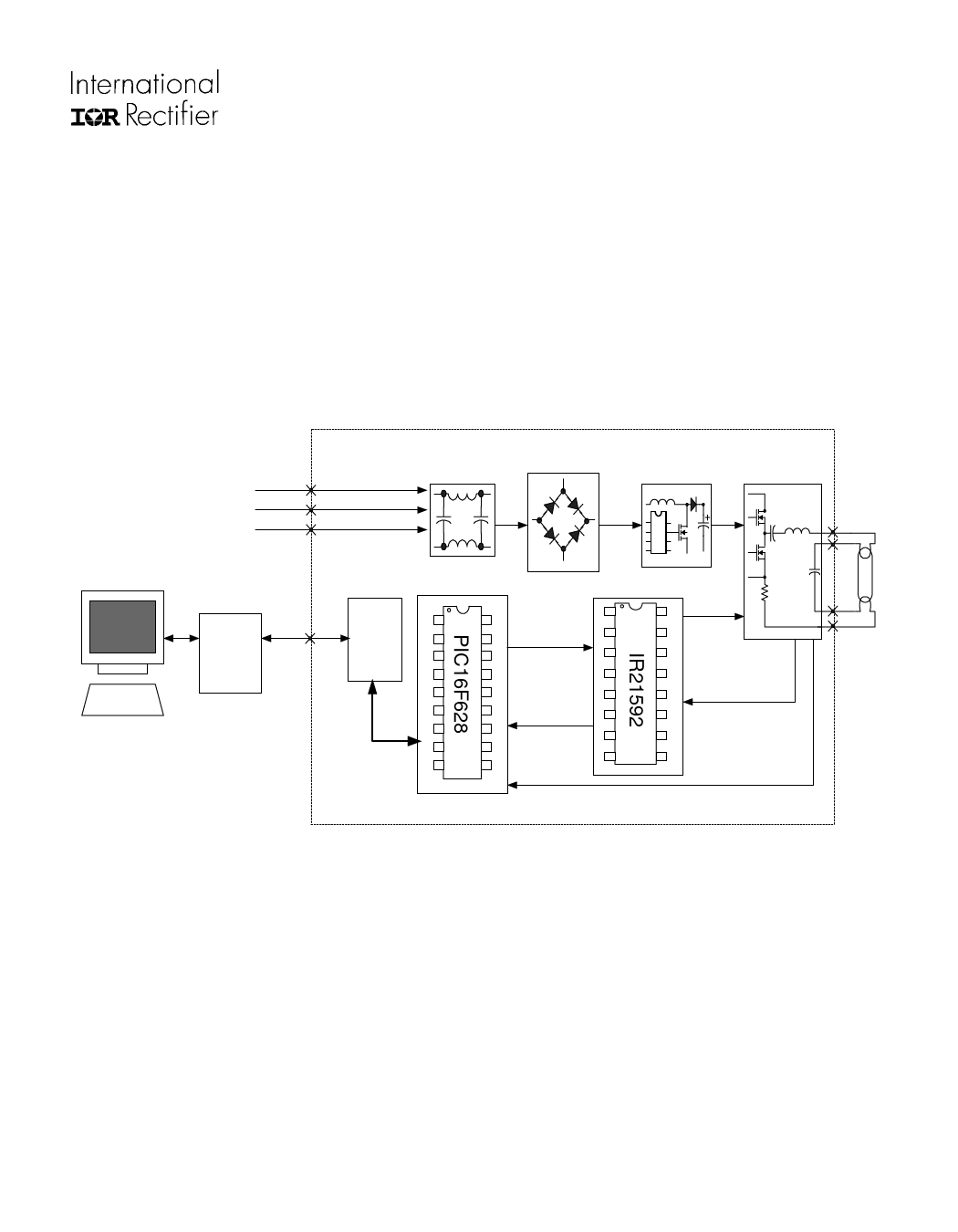
FUNCTIONAL DESCRIPTION
The IRPLDIM2E Demo Board consists of an EMI filter, an active power factor correction front end, a ballast
control section, a digital control section and a resonant lamp output stage. A block diagram of the design is shown
in Figure 3.
The EMI filter blocks ballast generated noise. The power factor correction is used for sinusoidal input current and
a regulated DC bus. The ballast control section provides frequency modulation control of a traditional RLC lamp
resonant output circuit for preheating, igniting and ballasting the lamp. It is easily adaptable to a wide variety of
lamp types. The digital control section provides the Digitally Addressable Lighting Interface (DALI) and the neces-
sary circuitry and software to perform closed-loop dimming, lamp fault detection, shutdown and auto-restart.
Rectifier
L
EMI Filter
PFC
Output Stage
N
E
PC
RS232/
DALI
converter
NOTE: Ballast can also be
connected directly to a DALI
compliant system..
PC and RS232/DALI converter
are used for demo purposes.
DALI
input
Interface
OPTO
Interface
Micro light level
1 RA2
RA118
Fade time
Fade rate
2 RA3
RA017
On/Off
3 RA4
RA716
4 RA5
5 VSS
6 RB0
7 RB1
RA615
VDD14
RB713
RB612
Fault condition
actual level
light status
ballast
8 RB2
RB511
9 RB3
RB410
IRPLDIM2 Reference Design
IR-IC
1 VDC
2 VCO
3 CPH
4 DIM
5 MAX
6 MIN
7
FMI
N
8 IPH
HO 16
VS 15
VB 14
VCC 13
CO
M
12
LO 11
CS 10
SD 9
Half Bridge
Driver
Dimming Feedback
Preheat Feedback
Lamp Fault
Lamp
Fig. 3 IRPLDIM2 Block diagram
You can connect the board directly to the DALI input (2 connections) or you can use the RS232/DALI converter
board (for demo purposes with the IRPLDIM2E board) to connect it to the PC.
The ballast control circuit uses the IR21592 Dimming Ballast Control IC programmed by the PIC16F628
microcontroller. The IR21592 controls the ballast according to the signals received from the microcontroller. The
microcontroller is connected to the ballast and the IC to receive diagnostic signals.
The communication between the ballast and the external world is done with two signals: TX (digital serial signal
transmitted from the network to the microcontroller) and RX (digital serial signal from the microcontroller to the
network). This system allows the ballast to communicate bi-directionally with the network (a PC or generally a
DALI system). A digital interface assures high voltage isolation between DALI inputs and the resonant lamp output
stage. The microcontroller manages the communication between interface and ballast IC.
The complete circuit is shown in Appendix A. In the circuit thick races represent high frequency and high current
paths. Lead lengths should be minimized to avoid high-frequency noise problems. Appendix B shows the Bill of
Materials.
www.irf.com
3
Share Link: 