LH1525 Просмотр технического описания (PDF) - Siemens AG
Номер в каталоге
Компоненты Описание
производитель
LH1525 Datasheet PDF : 25 Pages
| |||
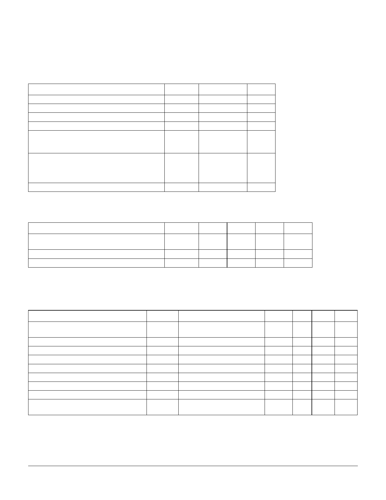
Absolute Maximum Ratings TA=25°C
Stresses exceeding the values listed under Absolute
Maximum Ratings can cause permanent damage to the
device. This is an absolute stress rating only. Functional
operation of the device at these or any other conditions
in excess of those indicated in the operational sections
of this data sheet is not implied. Exposure to maximum-
rating conditions for extended periods ot time can
adversely affect the device reliability.
Rating
Ambient Operating Temperature Range
Storage Temperature Range
Pin Soldering Temperature (t=7 s max.)
Input/Output Isolation Voltage (t=60 s min.)
LED Input Ratings:
Continuous forward current
Reverse voltage
Output Operation:
dc or peak ac load voltage (IL £ 50 mA)
Continuous dc load current
Peak load current (t=10 ms)
Power Dissipation
Symbol
TA
Tstg
TS
VISO
IF
VR
VL
IL
IP
PDISS
Value
–40 to +85
–40 to +100
270
1500
20
10
350
135
400
500
Unit
°C
°C
°C
Vrms
mA
V
V
mA
mA
mW
Recommended Operating Conditions TA=25°C
(unless otherwise specified)
Parameter
LED Forward Current for Switch Turn-on
(TA=–40°C to +85°C)
Continuous dc Load Current
ac rms Load Current
Symbol
Min
Typ
Max
Unit
IFON
8
10
20
mA
IL
—
45
135
mA
—
—
30
135
mA
Electrical Characteristics TA=25°C
Minimum and maximum values are testing require-
ments. Typical values are characteristics of the device
and are the result of engineering evaluations. Typical
values are for information purposes only and are not
part of the testing requirements.
Characteristics
LED Forward Current for Switch Turn-on
LED Forward Current for Switch Turn-off
LED Forward Voltage
ON-resistance
Current Limit
Ouput Off-state Leakage Current
Turn-on Time
Turn-off Time
Feedthrough Capacitance
Pin 4 to 6
Symbol
IFon
IFoff
VF
RON
ILMT
—
ton
toff
—
Test Condition
IL (min)=150 mA, VL=±9 V,
t=10 ms
IF=0.2 mA, VL=±300 V
IF=10 mA
IF=5 mA, IL= ±25 mA
IF=5 mA, VL=±9, t=10 ms
IF=0, VL=±100 V
IF=5 mA, VL=+150 V, RL=4 kW
IF=5 mA, VL=+150 V, RL=4 kW
IF=0, VL=4 Vp-p, 1 kHz
Min Typ Max Unit
—
1.3 2.5
mA
0.2
1.2 —
mA
1.15 1.22 1.45
V
20
30 37
W
225 300 400 mA
—
0.03 200
nA
—
1.4 2.0
ms
—
0.9 2.0
ms
—
24
—
pF
Siemens Microelectronics, Inc. • Optoelectronics Division
www.smi.siemens.com/opto/
25 of 25
LH1085AT1/AAB1
October 1998
Share Link: 