LT3599(RevD) –Я—А–Њ—Б–Љ–Њ—В—А —В–µ—Е–љ–Є—З–µ—Б–Ї–Њ–≥–Њ –Њ–њ–Є—Б–∞–љ–Є—П (PDF) - Linear Technology
–Э–Њ–Љ–µ—А –≤ –Ї–∞—В–∞–ї–Њ–≥–µ
–Ъ–Њ–Љ–њ–Њ–љ–µ–љ—В—Л –Ю–њ–Є—Б–∞–љ–Є–µ
–њ—А–Њ–Є–Ј–≤–Њ–і–Є—В–µ–ї—М
LT3599 Datasheet PDF : 26 Pages
| |||
LT3599
Applications Information
LED Current Dimming
Two different types of dimming control can be used with
the LT3599. The LED brightness can be set either by analog
dimming (CTRL pin voltage adjustment between 0V and 1V)
or PWM dimming (PWM pin duty cycle adjustment).
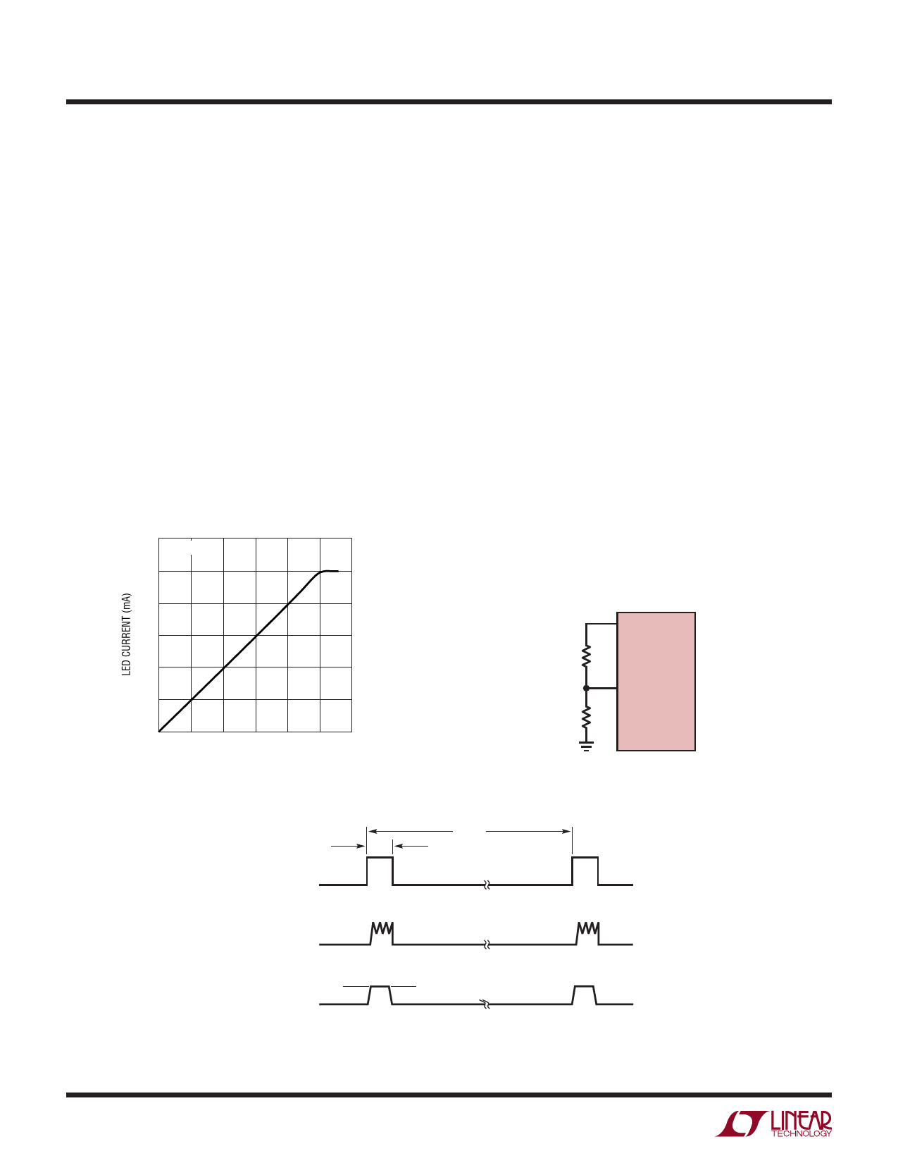
For some applications, the preferred method of brightness
control is to use a variable DC input voltage. The CTRL
pin voltage can be adjusted to set the dimming of the LED
string (see Figures 4 and 5). As the voltage on the CTRL
pin increases from 0V to 1V, the LED current increases
from 0 to the programmed LED current level. Once the
CTRL pin voltage increases beyond 1V, it has no effect on
the LED current.
For True Color PWM dimming, the LT3599 provides
up to a 3000:1 PWM dimming range by allowing the duty
cycle of the PWM pin to be reduced from 100% to as
120
ISET = 13.3k
100
80
60
40
20
0
0 0.2 0.4 0.6 0.8 1.0 1.2
CTRL PIN VOLTAGE (V)
3599 F04
Figure 4. LED Current vs CTRL Voltage
low as 0.033% at a PWM frequency of 100Hz (Figure 6).
Dimming by PWM duty cycle, allows for constant LED
color to be maintained over the entire dimming range.
For LT3599 PWM dimming control during startup and
normal operation, observe the following guidelines:
(1) STARTUP
LT3599 VOUT start-up requires the SHDN/UVLO pin to be
asserted from off to on and the PWM on-time to be above
a minimum value. The lowest PWM on-time allowed for
fault detection is вЙИ20¬µs. The lowest PWM on-time allowed
for reaching VOUT regulation is typically 20µs but might be
greater depending on external circuit parameters. Once LED
current is in regulation, PWM on-time can be reduced as
low as 3µs depending on external component selection.
(2) VOUT Collapse
If during normal operation VOUT collapses due to a fault
or because PWM on-time is too low, a re-start is required
(see STARTUP in item (1)).
VREF
R2
LT3599
CTRL
R1
3599 F05
Figure 5. LED Current vs CTRL
PWM
TPWM
TONPWM
(= 1/fPWM)
12
INDUCTOR
CURRENT
LED
CURRENT
MAX ILED
3599 F06
Figure 6. LED Current Using PWM Dimming
3599fd
Share Link: 