PC8240VTPU200E Просмотр технического описания (PDF) - Atmel Corporation
Номер в каталоге
Компоненты Описание
производитель
PC8240VTPU200E Datasheet PDF : 42 Pages
| |||
PC8240
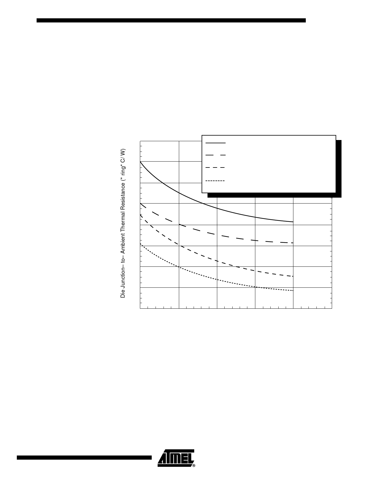
Figure 5 depicts the die junction-to-ambient thermal resistance for four typical cases:
1. A heat sink is not attached to the TBGA package and there exists high board-
level thermal loading of adjacent components.
2. A heat sink is not attached to the TBGA package and there exists low board-
level thermal loading of adjacent components.
3. A heat sink (e.g. ChipCoolers #HTS255-P) is attached to the TBGA package and
there exists high board-level thermal loading of adjacent components.
4. A heat sink (e.g. ChipCoolers #HTS255-P) is attached to the TBGA package and
there exists low board-level thermal loading of adjacent components.
Figure 5. Die Junction-to-Ambient Resistance
18
No heat sink and high thermal board–level loading of
adjacent components
No heat sink and low thermal board–level loading of
16
adjacent components
Attached heat sink and high thermal board–level loading
of adjacent components
14
Attached heat sink and low thermal board–level loading
of adjacent components
12
10
8
6
4
2
0
0.5
1
1.5
2
2.5
Airflow Velocity (m/s)
11
2149A–HIREL–05/02
Share Link: 