74LV4094 Просмотр технического описания (PDF) - Philips Electronics
Номер в каталоге
Компоненты Описание
производитель
74LV4094 Datasheet PDF : 14 Pages
| |||
Philips Semiconductors
8-stage shift-and-store bus register
Product specification
74LV4094
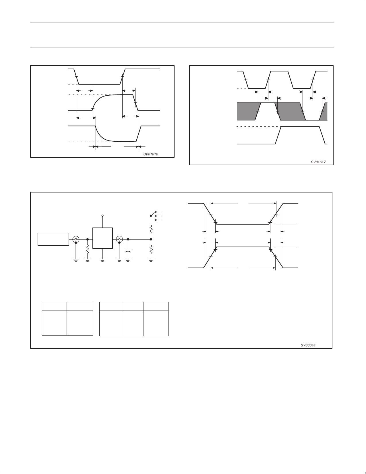
VCC
OE INPUT
VM
GND
VCC
OUTPUT
LOW-to-OFF
OFF-to-LOW
VOL
tPLZ
VX
tPHZ
VOH
OUTPUT
VY
HIGH-to-OFF
OFF-to-HIGH
GND
outputs
enabled
tPZL
VM
tPZH
outputs
disabled
VM
outputs
enabled
SV01618
Figure 3. 3-State enable and disable times for input OE.
VCC
CP INPUT
GND
VCC
D INPUT
GND
VOH
QPn, QS1, QS2 OUTPUT
VOL
VM
tsu
th
VM
VM
tsu
th
The shaded areas indicate when the input is permitted to change for predictable
output performance.
SV01617
Figure 4. Data set-up and hold times for the data input (D).
TEST CIRCUIT
Vcc
PULSE
GENERATOR
Vl
RT
VO
D.U.T.
Test Circuit for Outputs
S1
VS1
Open
GND
RL = 1k
CL= 50pF
RL = 1k
90%
NEGATIVE
PULSE
POSITIVE
PULSE
10%
tW
VM
10%
VM
10%
tTHL (tf)
tTLH (tr)
90%
VM
90%
VM
tW
VM = 1.5V
Input Pulse Definition
90%
VI
0V
tTLH (tr)
tTHL (tf)
VI
10%
0V
SWITCH POSITION
TEST
tPLH/tPHL
tPLZ/tPZL
tPHZ/tPZH
S1
Open
VS1
GND
VCC
< 2.7V
2.7–3.6V
≥ 4.5 V
VI
VCC
2.7V
VCC
VS1
2 < VCC
2 < VCC
2 < VCC
DEFINITIONS
RL = Load resistor
CL = Load capacitance includes jig and probe capacitance
RT = Termination resistance should be equal to ZOUT of
pulse generators.
Figure 5. Load circuitry for switching times.
SY00044
1998 Jun 23
10
Share Link: 