SP3223UCA/TR Просмотр технического описания (PDF) - Signal Processing Technologies
Номер в каталоге
Компоненты Описание
производитель
SP3223UCA/TR Datasheet PDF : 24 Pages
| |||
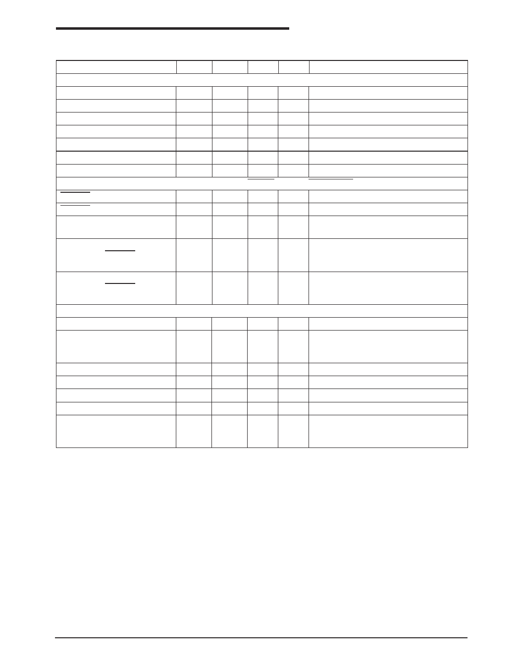
ELECTRICAL CHARACTERISTICS
Unless otherwise noted, the following specifications apply for VCC = +3.0V to +5.5V with TAMB = TMIN to TMAX,
C1 - C4 = 0.1µF. Typical values apply at VCC = +3.3V or +5.0V and TAMB = 25°C.
PARAMETER
MIN. TYP. MAX. UNITS CONDITIONS
RECEIVER INPUTS
Input Voltage Range
-25
25
V
Input Threshold LOW
Input Threshold LOW
0.6
1.2
0.8
1.5
V VCC = 3.3V
V VCC = 5.0V
Input Threshold HIGH
1.5
2.4
V VCC = 3.3V
Input Threshold HIGH
Input Hysteresis
1.8
2.4
V VCC = 5.0V
0.3
V
Input Resistance
3
5
7
kΩ
AUTO ON-LINE® CIRCUITRY CHARACTERISTICS (ONLINE = GND, SHUTDOWN = VCC)
STATUS Output Voltage LOW
0.4
V IOUT = 1.6mA
STATUS Output Voltage HIGH VCC - 0.6
V IOUT = -1.0mA
Receiver Threshold to Drivers
Enabled (tONLINE)
200
µS Figure 19
Receiver Positive or Negative
Threshold to STATUS HIGH
(tSTSH)
Receiver Positive or Negative
Threshold to STATUS LOW
(tSTSL)
TIMING CHARACTERISTICS
0.5
µS Figure 19
20
µS Figure 19
Maximum Data Rate
Receiver Propagation Delay
tPHL
tPLH
Receiver Output Enable Time
1000
0.15
0.15
200
Kbps RL = 3KΩ, CL = 250pF, one driver active
µs Receiver input to Receiver output, CL = 150pF
ns Normal operation
Receiver Output Disable Time
200
ns Normal operation
Driver Skew
Receiver Skew
100
ns | tPHL - tPLH |
50
ns | tPHL - tPLH |
Transition-Region Slew Rate
90
V/µs VCC = 3.3V, RL = 3KΩ, TAMB = 25°C,
measurements taken from -3.0V to +3.0V or
+3.0V to -3.0V
Date: 5/25/04
SP3223U/3243U +3.0V to +5.5V RS-232 Transceivers
3
© Copyright 2004 Sipex Corporation
Share Link: 