TS4601B Просмотр технического описания (PDF) - STMicroelectronics
Номер в каталоге
Компоненты Описание
производитель
TS4601B
STMicroelectronics
TS4601B Datasheet PDF : 28 Pages
| |||
TS4601B
Typical application schematics
Table 3. Pin description for the TS4601B (continued)
Pin number
Pin name
Pin definition
C3
INR+
Right audio channel positive input signal.
D3
SDA
I²C signal data. Up to VCC tolerant input.
D2
SCL
I²C clock signal. Up to VCC tolerant input.
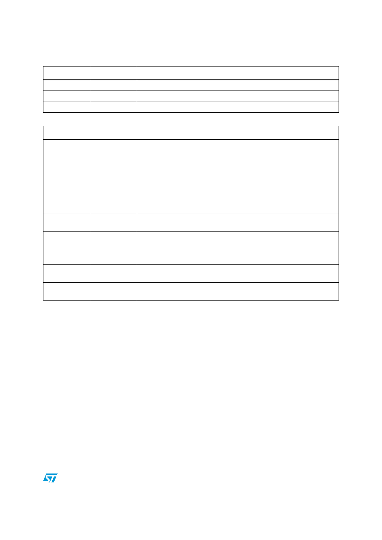
Table 4. Component description for the TS4601B
Component
Value
Description
Decoupling capacitors for VCC and PVCC. Two 1µF capacitors are enough for
proper decoupling of TS4601B. X5R dielectric and 10V rating voltage is
Cs
1µF
recommended to minimize ΔC/ΔV when VCC= 5V.
Must be placed as close as possible to the TS4601B to minimize parasitic
inductance and resistance.
Capacitor for internal negative power supply operation. X5R dielectric and 10V
C12
1µF
rating voltage is recommended to minimize ΔC/ΔV when VCC= 5V.
Must be placed as close as possible to the TS4601B to minimize parasitic
inductance and resistance.
CSS
2.2µF
Filtering capacitor for internal negative power supply. X5R dielectric and 10V
rating voltage is recommended to minimize ΔC/ΔV when VCC = 5V.
Cin
Cin = -2---π----Z---1-i--n----F----c-
Input coupling capacitor that forms with Zin, a first order high pass filter with a
-3dB cut-off frequency FC. Zin is 12kΩ typical and independent of the gain
setting.
For example FC = 13Hz, Cin = 1µF and for FC = 6Hz, Cin = 2.2µF
Cout
0.8nF to 100nF
Output capacitor of 0.8nF minimum to 100nF maximum. This capacitor is
mandatory for operation of the TS4601B.
Rout
12Ω min.
Output resistor in series with the TS4601B output. This 12Ω minimum resistor
is mandatory for operation of the TS4601B.
5/28
Share Link: 