TW9903 Просмотр технического описания (PDF) - Unspecified
Номер в каталоге
Компоненты Описание
производитель
TW9903 Datasheet PDF : 74 Pages
| |||
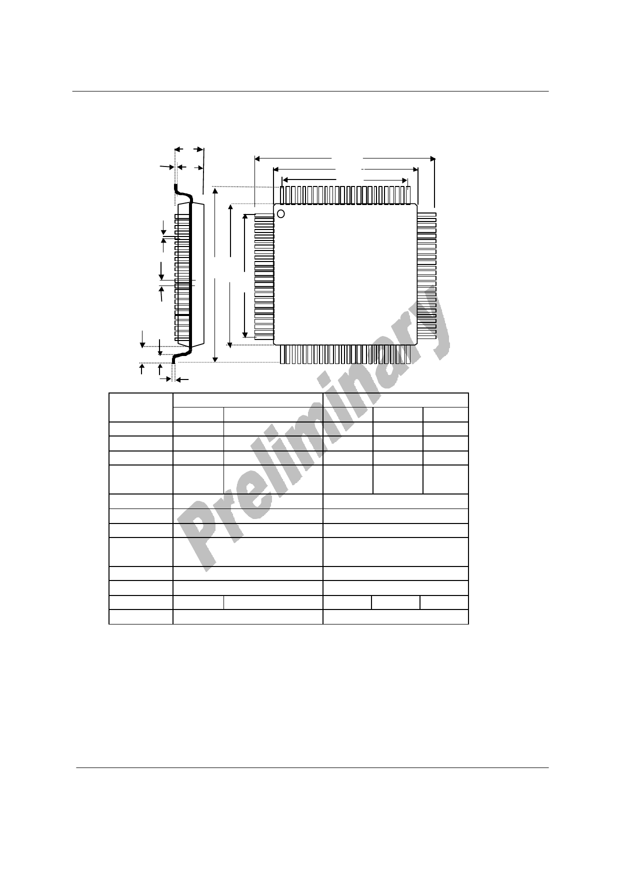
TW9903
100-pin LQFP Package Mechanical Drawing
A
A1
1
A2
E
E1
E2
b
D D1
e
D2
TW9903
Top
View
L
L1
Symbol
A
A1
A2
b
c
e
D
D1
D2
E
E1
E2
L
L1
c
Millimeter
Min. Nom. Max.
---
--- 1.60
0.05
---
0.15
1.35 1.40 1.45
0.13 0.16 0.23
0.09 0.10 0.20
0.4 Basic
14.0 Basic
12.00 Basic
9.60
14.0 Basic
12.00 Basic
9.60
0.45 0.60 0.75
1.00 Ref
Inch
Min. Nom. Max.
---
--- 0.063
0.002 --- 0.006
0.053 0.055 0.057
0.005 0.006 0.009
0.004 --- 0.008
0.016 Basic
0.551 Basic
0.472 Basic
0.378
0.551Basic
0.472 Basic
0.378
0.018 0.024 0.030
0.039Ref
Note: 1. Dimension of D1 and E1 do not include mold protrusion. Allowable protrusion is 0.25mm per side.
Dimension D1 and E1 do include mold mismatch and are determined at datum plane.
2. Dimension b does not include dambar protrusion. Allowable dambar protrusion shall not cause the
lead width to exceed. The maximum b dimension by more than 0.08mm dambar cannot be located on the lower
radius or the lead root.
TECHWELL, INC.
74
REV. 0.92 ( B )
06/02/2002
Share Link: 