DMS-20PC –ü—Ä–æ—Å–º–æ—Ç—Ä —Ç–µ—Ö–Ω–∏—á–µ—Å–∫–æ–≥–æ –æ–ø–∏—Å–∞–Ω–∏—è (PDF) - Murata Power Solutions
–ù–æ–º–µ—Ä –≤ –∫–∞—Ç–∞–ª–æ–≥–µ
–ö–æ–º–ø–æ–Ω–µ–Ω—Ç—ã –û–ø–∏—Å–∞–Ω–∏–µ
–ø—Ä–æ–∏–∑–≤–æ–¥–∏—Ç–µ–ª—å
DMS-20PC
Murata Power Solutions
DMS-20PC Datasheet PDF : 6 Pages
| |||
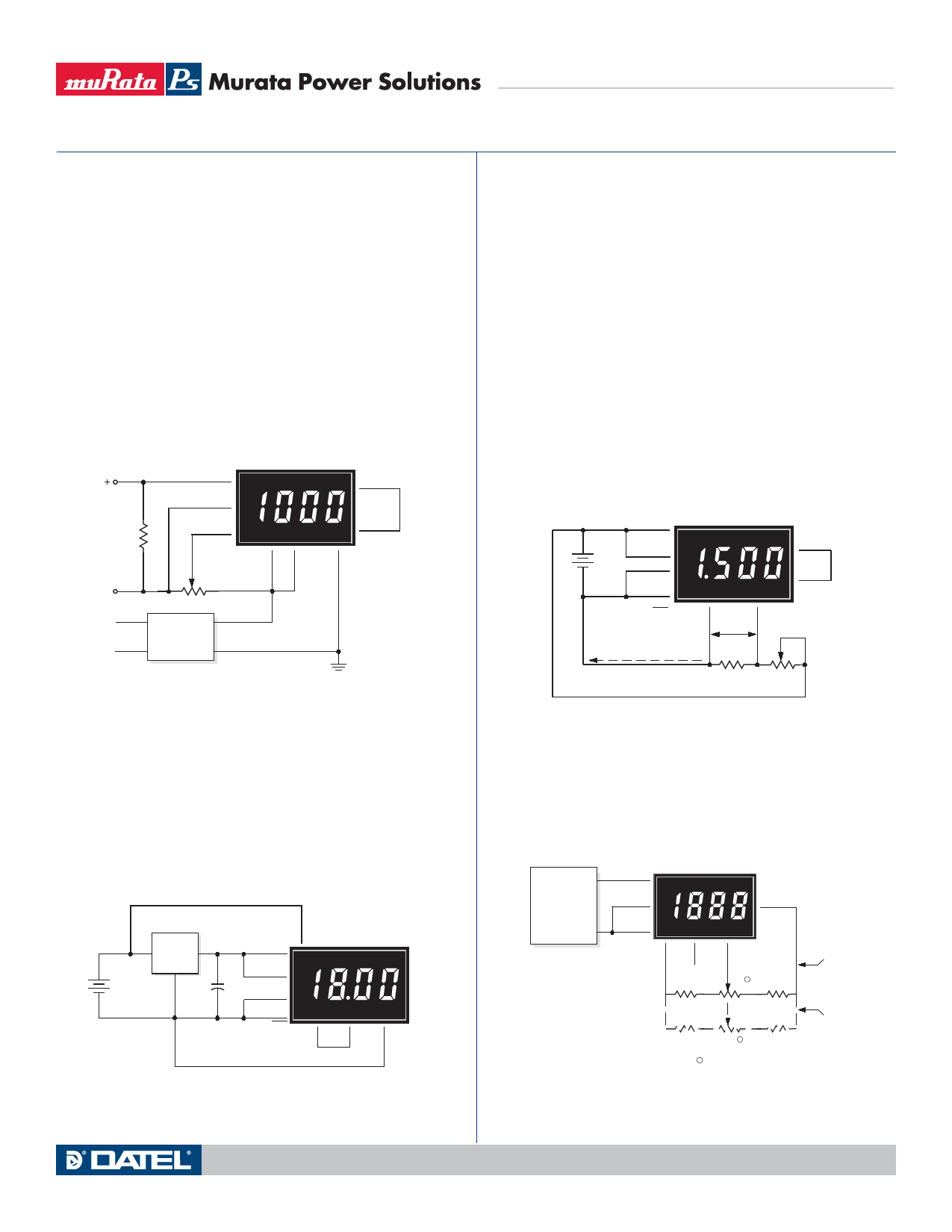
APPLICATIONS
Example: For a meter with a 2V full scale input (1.999 full scale
reading) and a desired display reading of "1000" (with an
input of 20mA), VFsr = 1.000 Volts
RShunt = 1.000V/(0.020 – 0.004)A
RShunt= 1.000V/0.016A = 62.5 Ohms
To calibrate the circuit of Figure 7, perform the following:
1. With 4mA applied, adjust the 50kΩ potentiometer (R2) to
display a reading of "000" (assuming that is the desired
reading).
2. With 20mA applied, adjust the gain-adjust potentiometer
on the back of the meter to display a reading of "1000".
For different full scale readings, alter the value of RShunt
accordingly.
11
(+) IN HI
10
ANA COMM
DMS-20PC-1
8
REF OUT
4-20mA R1
–
12
(–) IN LO
1
R2
+5V SUP
50k
7
REF IN
2
DISPLAY
ENABLE
3
5V RET
DATEL
85-264Vac DMS-PS1-CM
AC to DC Converter
Figure 7. 4-to-20mA Current Loop Operation
6. Power Supply Monitoring: One of the most common digital
panel meter applications involves monitoring the output voltage
of the system power supply — often this supply also powers the
meter itself. The low-power, red LED DMS-20PC-2-RL can be
configured to allow power supply monitoring over the range of
4.5-18Vdc. The circuit in Figure 8 uses a low-drop-out, three-ter-
minal regulator (LM-2931Z-5, available from National Semicon-
ductor) to provide regulated 5V-power to the meter.
LM2931Z-5
IN OUT
+
GND
+
4.5 - 18Vdc
22μF
–
10V
DMS-20PC-2-RL
1
+5V SUP
2
DISP EN
3
5V RET
11 (+) IN HI
5
DP2
7
REF
IN
8
REF
OUT
12
(–) IN LO
Figure 8. 4.5-18V Power Supply Monitor
DMS-20PC Series
3¬Ω Digit, LED Display, Low-Cost, Subminiature
Digital Panel Voltmeters
The LM-2931 was chosen because it has the following on-chip
protection features: reverse polarity, short circuit and thermal
runaway. When using other, higher-power, DMS-20PC models
with three-terminal regulators, be sure to consult the regula-
tor manufacturer's data sheet to ensure the regulator is being
utilized safely and correctly.
7. Digital Ammeter: Digital ammeters are finding ever-increasing
usage because analog-style ammeters (moving-vane types)
now cost roughly the same as their digital counterparts. Addi-
tionally, analog ammeters are not nearly as rugged as modern
digital panel voltmeters. Figure 9 illustrates a typical ammeter
application. The circuit uses a ±200mV input meter — the
preferred range for most ammeters — to measure the voltage
developed across a 0.1Ω current shunt. The circuit shown
represents a basic ammeter connection diagram. A detailed
application note describing digital dc ammeters is included in
DATEL's new Digital Panel Meter Databook.
+
5Vdc
–
1
+5V SUP
2
DISP EN
DMS-20PC-0
8
REF OUT
3
5V RET
6
DP1
12
(–) IN LO
7
REF IN
11
(+) IN HI
1.5 Amp (Load Current)
0.150V
0.1W
RShunt
Load
(3.3 W)
Figure 9. Basic DC Ammeter Circuit
8. External Gain Adjustment: Connect REFERENCE OUT
(pin 8) to REFERENCE IN (pin 7) for normal, factory calibrated,
operation. Use the circuit shown in Figure 10 for applications
needing external gain adjustment. Calibration is performed
with a precise, near-full-scale, input voltage.
OUT
12
VOLTAGE
CALIBRATOR
COM
11
(+) IN HI
3
5V RET
DMS-20PC-1
1
+5V IN
12
(–) IN LO
10
ANA
COMM
8
7
NC REF
IN
8.06k, 1%
Connections
for ±2V, ±20V
and ±200V models
2k 1 17.4k, 1%
732, 1%
200 1
24.3k, 1%
Connections
for ±200mV
models
1 = 10 to 20 Turns
Figure 10. External Gain Adjustment
www.murata-ps.com
Technical enquiries email: sales@murata-ps.com, tel: +1 508 339 3000
MPM_DMS_20PC.D02 Page 5 of 6
Share Link: 