MAX1636EAP Просмотр технического описания (PDF) - Maxim Integrated
Номер в каталоге
Компоненты Описание
производитель
MAX1636EAP Datasheet PDF : 23 Pages
| |||
Low-Voltage, Precision Step-Down
Controller for Portable CPU Power
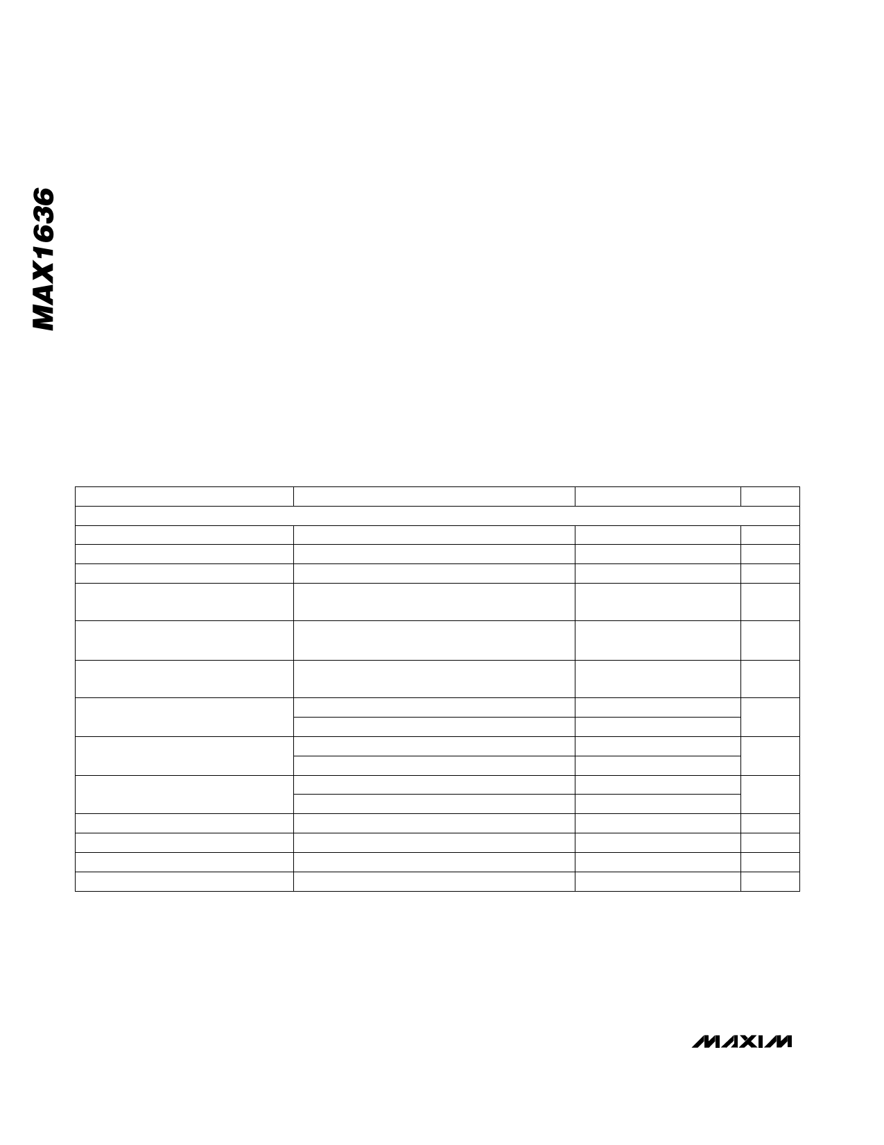
ABSOLUTE MAXIMUM RATINGS
V+ to GND ...............................................................-0.3V to 36V
GND to PGND........................................................................±2V
SHDN to GND. ......................................................... -0.3V to 36V
LX, BST to GND. ...................................................... -0.3V to 36V
DH, BST to LX .............................................................-0.3V to 6V
VL, VCC, CSL, CSH, FB, SKIP to GND ...................... -0.3V to 6V
DL to GND.. ..................................................-0.3V to (VL + 0.3V)
REF, RESET, SYNC, CC, OVP to GND. ..... -0.3V to (VCC + 0.3V)
VL Output Current... ............................................................50mA
VL Short Circuit to GND..............................................Momentary
REF Output Current ............................................................20mA
REF Short Circuit to GND ....... ......................................Indefinite
Continuous Power Dissipation (TA = +70°C)
SSOP (derate 8.00mW/°C above +70°C) .....................640mW
Operating Temperature Range
MAX1636EAP. ..................................................-40°C to +85°C
Storage Temperature Range .............................-65°C to +160°C
Junction Temperature ......................................................+150°C
Lead Temperature (soldering, 10s) .................................+300°C
Stresses beyond those listed under “Absolute Maximum Ratings” may cause permanent damage to the device. These are stress ratings only, and functional
operation of the device at these or any other conditions beyond those indicated in the operational sections of the specifications is not implied. Exposure to
absolute maximum rating conditions for extended periods may affect device reliability.
ELECTRICAL CHARACTERISTICS
(Circuit of Figure 1, V+ = 15V, SYNC = VL = VCC, IVL = 0mA, IREF = 0mA, TA = 0°C to +85°C, unless otherwise noted. Typical values
are at TA = +25°C.)
PARAMETER
CONDITIONS
MIN TYP MAX
UNITS
SMPS CONTROLLER
Input Voltage Range, V+
Input source for VL regulator
4.5
30
V
Input Voltage Range, VL
Gate-driver supply rail
4.2
5.5
V
Input Voltage Range, VCC
Internal chip supply rail
3.15
5.5
V
Output Voltage, Adj Mode
FB tied to VOUT, 0mV < (CSH - CSL) < 80mV, 4.5V
< V+ < 30V (includes line and load regulation)
1.090
1.100
1.110
V
Output Voltage, Fixed 2.5V Mode
FB tied to VCC, 0mV < (CSH - CSL) < 80mV, 4.5V
< V+ < 30V (includes line and load regulation)
2.486
2.55
2.614
V
Output Voltage, Fixed 3.3V Mode
FB tied to GND, 0mV < (CSH - CSL) < 80mV, 4.5V
< V+ < 30V (includes line and load regulation)
3.282
3.366
3.450
V
Output Adjustment Range
Current-Limit Threshold
VCC = VL = 5V
VCC = 3.3V, VL = 5V
Positive direction
Negative direction
VREF
VREF
5.5
V
3.6
80
100
120
mV
-145 -100
-55
mV
Power Consumption
Shutdown Supply Current (V+)
FB Input Current
Soft-Start Ramp Time
Idle Mode Switchover Threshold
VCC = 5V, output not switching
VCC = 3.3V, output not switching
SHDN = GND, OVP = GND
FB forced to REF
SHDN to full current limit, five levels
CSH - CSL
2.0
mW
1.5
3
10
µA
-50
50
nA
512
clks
20
30
40
mV
2 _______________________________________________________________________________________
Share Link: 