74LVT241 查看數據表(PDF) - NXP Semiconductors.
零件编号
产品描述 (功能)
生产厂家
74LVT241 Datasheet PDF : 16 Pages
| |||
NXP Semiconductors
74LVT241
3.3 V octal buffer/line driver; 3-state
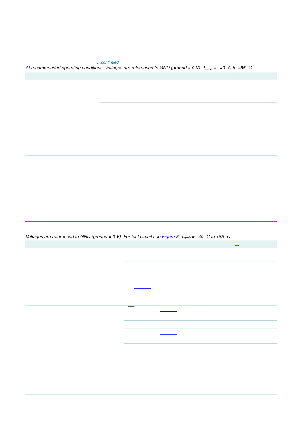
Table 6. Static characteristics …continued
At recommended operating conditions. Voltages are referenced to GND (ground = 0 V); Tamb = −40 °C to +85 °C.
Symbol Parameter
Conditions
Min
Typ[1] Max Unit
ICC
supply current
VCC = 3.6 V; VI = VCC or GND; IO = 0 A
outputs HIGH
-
0.12
0.19 mA
outputs LOW
-
3
12
mA
outputs disabled
[5] -
0.12
0.19 mA
∆ICC
CI
CI/O
additional supply current per input pin; VCC = 3.0 V to 3.6 V;
[6] -
one input = VCC − 0.6 V other inputs at
VCC or GND
input capacitance
1OE and 2OE inputs; outputs disabled;
-
VI = 0 V or 3.0 V
input/output capacitance at input/output data pins, outputs disabled;
-
VI/O = 0 V or 3.0 V
0.1
0.25 mA
4
-
pF
8
-
pF
[1] All typical values are measured at Tamb = 25 °C.
[2] Unused pins at VCC or GND.
[3] This is the bus hold overdrive current required to force the input to the opposite logic state.
[4] This parameter is valid for any VCC between 0 V and 1.2 V with a transition time of up to 10 ms. From VCC = 1.2 V to VCC = 3.3 V ± 0.3 V
a transition time of 100 ms is permitted. This parameter is valid for Tamb = +25 °C only.
[5] ICC with the outputs disabled is measured with outputs pulled to VCC or GND.
[6] This is the increase in supply current for each input at the specified voltage level other than VCC or GND.
10. Dynamic characteristics
Table 7. Dynamic characteristics
Voltages are referenced to GND (ground = 0 V). For test circuit see Figure 8; Tamb = −40 °C to +85 °C.
Symbol Parameter
Conditions
Min Typ[1]
tPLH
LOW to HIGH propagation delay
1An to 1Yn, 2An to 2Yn;
see Figure 5
tPHL
HIGH to LOW propagation delay
VCC = 2.7 V
VCC = 3.3 V ± 0.3 V
1An to 1Yn, 2An to 2Yn;
see Figure 5
-
-
1.0
2.8
VCC = 2.7 V
VCC = 3.3 V ± 0.3 V
tPZH
OFF-state to HIGH propagation delay 1OE to 1Yn; see Figure 6
VCC = 2.7 V
VCC = 3.3 V ± 0.3 V
2OE to 2Yn; see Figure 7
-
-
1.0
2.8
-
-
1.0
3.2
VCC = 2.7 V
VCC = 3.3 V ± 0.3 V
-
-
1.0
3.8
Max Unit
4.0 ns
3.8 ns
4.0 ns
3.8 ns
5.0 ns
4.4 ns
5.6 ns
5.1 ns
74LVT241_3
Product data sheet
Rev. 03 — 7 May 2008
© NXP B.V. 2008. All rights reserved.
6 of 16
Share Link: 