A8514KLPTR-T 查看數據表(PDF) - Allegro MicroSystems
零件编号
产品描述 (功能)
生产厂家
A8514KLPTR-T Datasheet PDF : 35 Pages
| |||
A8514
Wide Input Voltage Range, High Efficiency
Fault Tolerant LED Driver
Although the APWM dimming function has a wide frequency
range, if this function is used strictly as an analog dimming
function it is recommended to use frequency ranges between
50 and 500 kHz for best accuracy. The frequency range must be
considered only if the user is not using this function as a closed
loop trim function. Another limitation is that the propagation
delay between this APWM signal and IOUT takes several milli-
seconds to change the actual LED current. This effect is shown in
figures 16, 17, and 19.
Analog dimming
The A8514 can also be dimmed by using an external DAC or
another voltage source applied either directly to the ground side
of the RISET resistor or through an external resistor to the ISET
pin (see figure 19). The limit of this type of dimming depends on
the range of the ISET pin. In the case of the A8514 the limit is
20 to 125 μA.
• For a single resistor (panel A of figure 20), the ISET current is
controlled by the following formula:
ISET
=
VISET – VDAC
RISET
(3)
where VISET is the ISET pin voltage and VDAC is the DAC output
voltage.
When the DAC voltage is 0 V the LED current will be at its
maximum. To keep the internal gain amplifier stable, the user
should not decrease the current through the RISET resistor to less
than 20 μA
• For a dual-resistor configuration (panel B of figure 20), the ISET
current is controlled by the following formula:
ISET
=
VISET
RISET
–
VDAC – VISET
R1
(4)
The advantage of this circuit is that the DAC voltage can be
higher or lower, thus adjusting the LED current to a higher or
lower value of the preset LED current set by the RISET resistor:
▫ VDAC = 1.003 V; the output is strictly controlled by RISET
▫ VDAC > 1.003 V; the LED current is reduced
▫ VDAC < 1.003 V; the LED current is increased
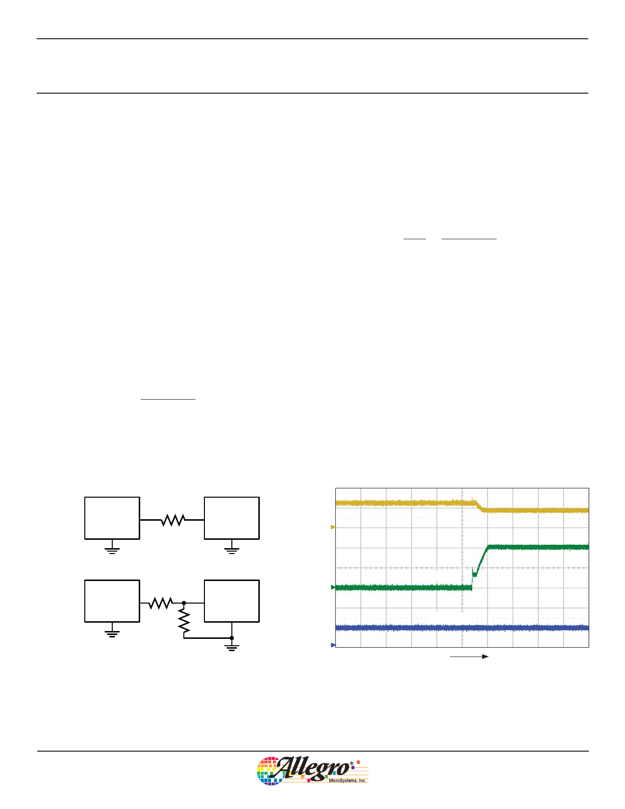
LED short detect
Both LEDx pins are capable of handling the maximum VOUT
that the converter can deliver, thus providing protection from the
LEDx pin to VOUT in the event of a connector short.
An LEDx pin that has a voltage exceeding VLEDSC will be
removed from operation (see figure 21). This is to prevent the IC
from dissipating too much power by having a large voltage pres-
ent on an LEDx pin.
DAC
VDAC
GND
RISET
(A)
A8514
ISET
GND
DAC
VDAC
GND
R1
RISET
A8514
ISET
GND
(B)
Figure 20. Simplified diagrams of voltage control of ILED: typical
applications using a DAC to control ILED using a single resistor (upper),
and dual resistors (lower).
IOUT
C1
LED1
C2
PWM/EN
C3
t
Figure 21. Example of the disabling of an LED string when the LED pin
voltage is increased above 4.6 V; shows IOUT (ch1, 200 mA/div.), LED1
(ch2, 5 V/div.), and PWM/EN (ch3, 5 V/div.), time = 10 μs/div.
Allegro MicroSystems, Inc.
18
115 Northeast Cutoff
Worcester, Massachusetts 01615-0036 U.S.A.
1.508.853.5000; www.allegromicro.com
Share Link: 