ADC1003S040 查看數據表(PDF) - NXP Semiconductors.
零件编号
产品描述 (功能)
生产厂家
ADC1003S040
NXP Semiconductors.
ADC1003S040 Datasheet PDF : 20 Pages
| |||
NXP Semiconductors
ADC1003S030/040/050
Single 10 bits ADC, up to 30 MHz, 40 Mhz or 50 MHz, with voltage
regulator
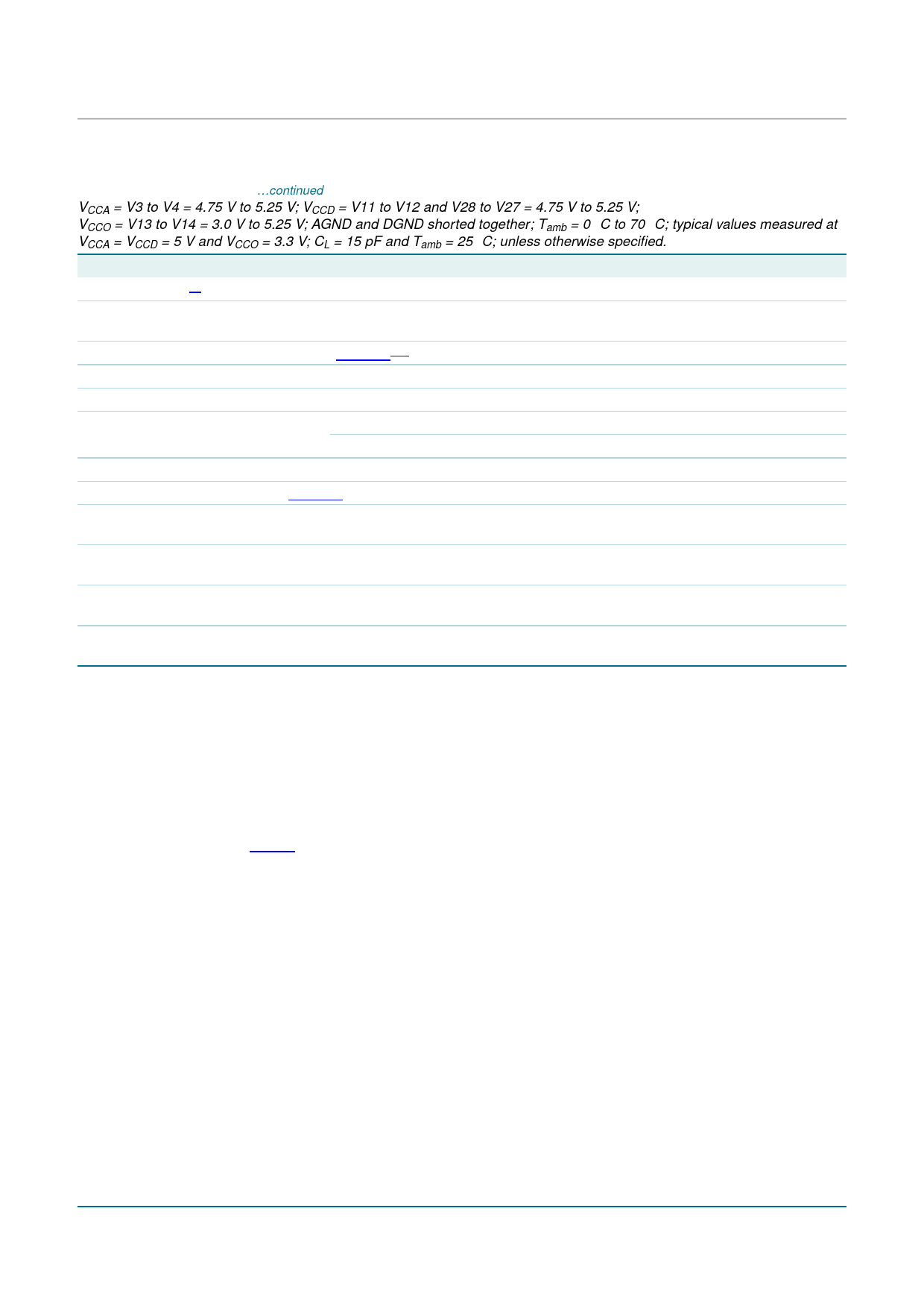
Table 6. Characteristics …continued
VCCA = V3 to V4 = 4.75 V to 5.25 V; VCCD = V11 to V12 and V28 to V27 = 4.75 V to 5.25 V;
VCCO = V13 to V14 = 3.0 V to 5.25 V; AGND and DGND shorted together; Tamb = 0 °C to 70 °C; typical values measured at
VCCA = VCCD = 5 V and VCCO = 3.3 V; CL = 15 pF and Tamb = 25 °C; unless otherwise specified.
Symbol Parameter
Conditions
Min
Typ
Max
Unit
Differential phase[9]
ϕdif
differential phase
fclk = 40 MHz;
-
0.4
-
deg
PAL modulated ramp
Timing (fclk = 40 MHz; CL = 15 pF); see Figure 4[10]
td(s)
sampling delay time
th(o)
output hold time
td(o)
output delay time
VCCO = 4.75 V
VCCO = 3.15 V
CL
load capacitance
3-state output delay times; see Figure 5
-
3
-
ns
4
-
-
ns
-
10
13
ns
-
12
15
ns
-
-
15
pF
tdZH
float to active HIGH delay
time
-
5.5
8.5
ns
tdZL
float to active LOW delay
time
-
12
15
ns
tdHZ
active HIGH to float delay
time
-
19
24
ns
tdLZ
active LOW to float delay
time
-
12
15
ns
[1] In addition to a good layout of the digital and analog ground, it is recommended that the rise and fall times of the clock must not be less
than 0.5 ns
[2] Analog input voltages producing code 0 up to and including code 1023:
a) Voffset BOTTOM is the difference between the analog input which produces data equal to 00 and the reference voltage on pin RB
(VRB) at Tamb = 25 °C.
b) Voffset TOP is the difference between reference voltage on pin RT (VRT) and the analog input which produces data outputs equal to
code 1023 at Tamb = 25 °C.
[3] In order to ensure the optimum linearity performance of such converter architecture the lower and upper extremities of the converter
reference resistor ladder (corresponding to output codes 0 and 1023 respectively) are connected to pins RB and RT via offset resistors
ROB and ROT as shown in Figure 3.
a) The current flowing into the resistor ladder is I L = -R---O---V-B----R-+--T--R--–--L---V--+--R--R-B---O----T-- and the full-scale input range at the converter
to cover code 0 to code 1023, is V I = RL × I L = -R---O----B-----+----R-R---LL----+-----R----O----T-- × (V RT – V RB) = 0.848 × (V RT – V RB)
b) Since RL, ROB and ROT have similar behavior with respect to process and temperature variation, the ratio -R---O----B-----+----R-R---LL----+-----R----O----T-- will
be kept reasonably constant from device to device. Consequently, variation of the output codes at a given input voltage depends
mainly on the difference VRT − VRB and its variation with temperature and supply voltage. When several ADCs are connected in
parallel and fed with the same reference source, the matching between each of them is optimized.
[4] EG = (---V----1---0--2--3----–-V----Vi--(--0P---)-–--–-P----)V----i--(--P----–---P---) × 100
[5] The analog bandwidth is defined as the maximum input sine wave frequency which can be applied to the device. No glitches greater
than 2 LSB, neither any significant attenuation are observed in the reconstructed signal.
[6] The analog input settling time is the minimum time required for the input signal to be stabilized after a sharp full-scale input (square
wave signal) in order to sample the signal and obtain correct output data.
ADC1003S030_040_050_2
Product data sheet
Rev. 02 — 7 August 2008
© NXP B.V. 2008. All rights reserved.
9 of 20
Share Link: 