AP2001SL-U 查看數據表(PDF) - Diodes Incorporated.
零件编号
产品描述 (功能)
生产厂家
AP2001SL-U Datasheet PDF : 8 Pages
| |||
AP2001
MONOLITHIC DUAL CHANNEL PWM CONTROLLER
Electrical Characteristics ( Continued )
Output section
Symbol
Parameter
Conditions
ILEAK
Leakage Current
VO = 40V
VSAT
Output Saturation Voltage IO = 10 mA
ISC
Short-circuit Output Current
PWM comparator
Symbol
Parameter
VO = 6V
Conditions
VT0
VT100
Total device
Symbol
Input Threshold Voltage at f = Zero duty cycle
10 KHz (FB)
Maximum duty cycle
Parameter
Conditions
ICCS
Standby Supply Current
Off-state
ICCA
Average Supply Current
RT = 10 KΩ
Min. Typ. Max. Unit
10 µA
1.2
2
V
90
mA
Min.
1.2
Typ.
2.05
1.45
Max. Unit
2.25 V
V
Min.
Typ.
2.5
2.8
Max. Unit
3.0 mA
3.5 mA
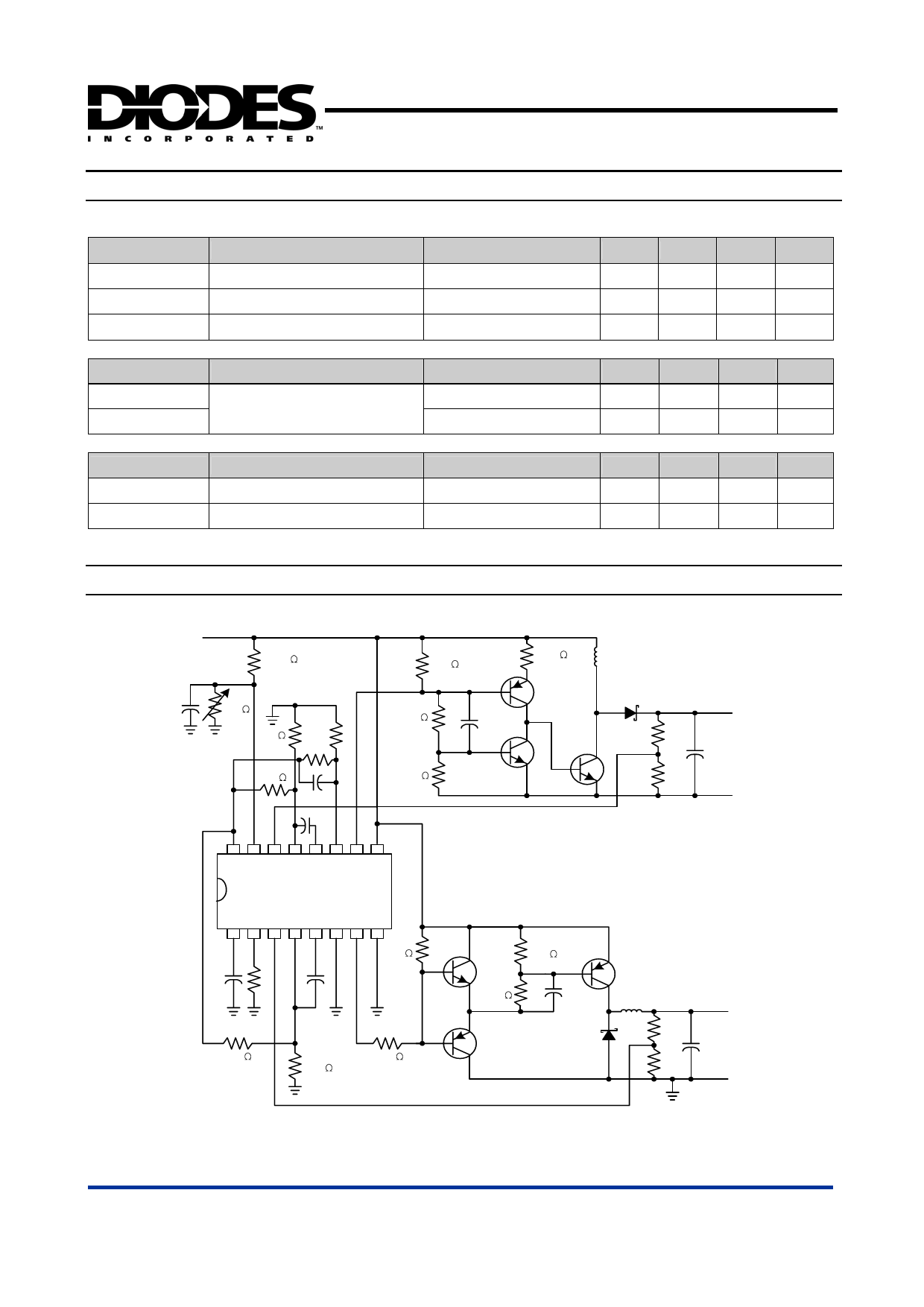
Typical Application Circuit
VCC
200k
470
0.47uF
50k
33k
R1
R2
33k
C1
500pF
V ref
16 15 14 13 12 11 10 9
33k
22k
AP2001
150
330pF
L1
R3
R4
Boost Output
C2
Note:
Values for R1 through R7 , C1 through C4 , and
L1 and L2 depend upon individual application.
12345678
470
C5
R5
500
pF
33k
470
33k
470
220
1uF
L2
R6
R7
Buck Output
C4
AP2001 Rev. 1
Dual output DC/DC converter
6 of 8
www.diodes.com
NOVEMBER 2006
© Diodes Incorporated
Share Link: 