APA4838 查看數據表(PDF) - Anpec Electronics
零件编号
产品描述 (功能)
生产厂家
APA4838
Anpec Electronics
APA4838 Datasheet PDF : 29 Pages
| |||
APA4838
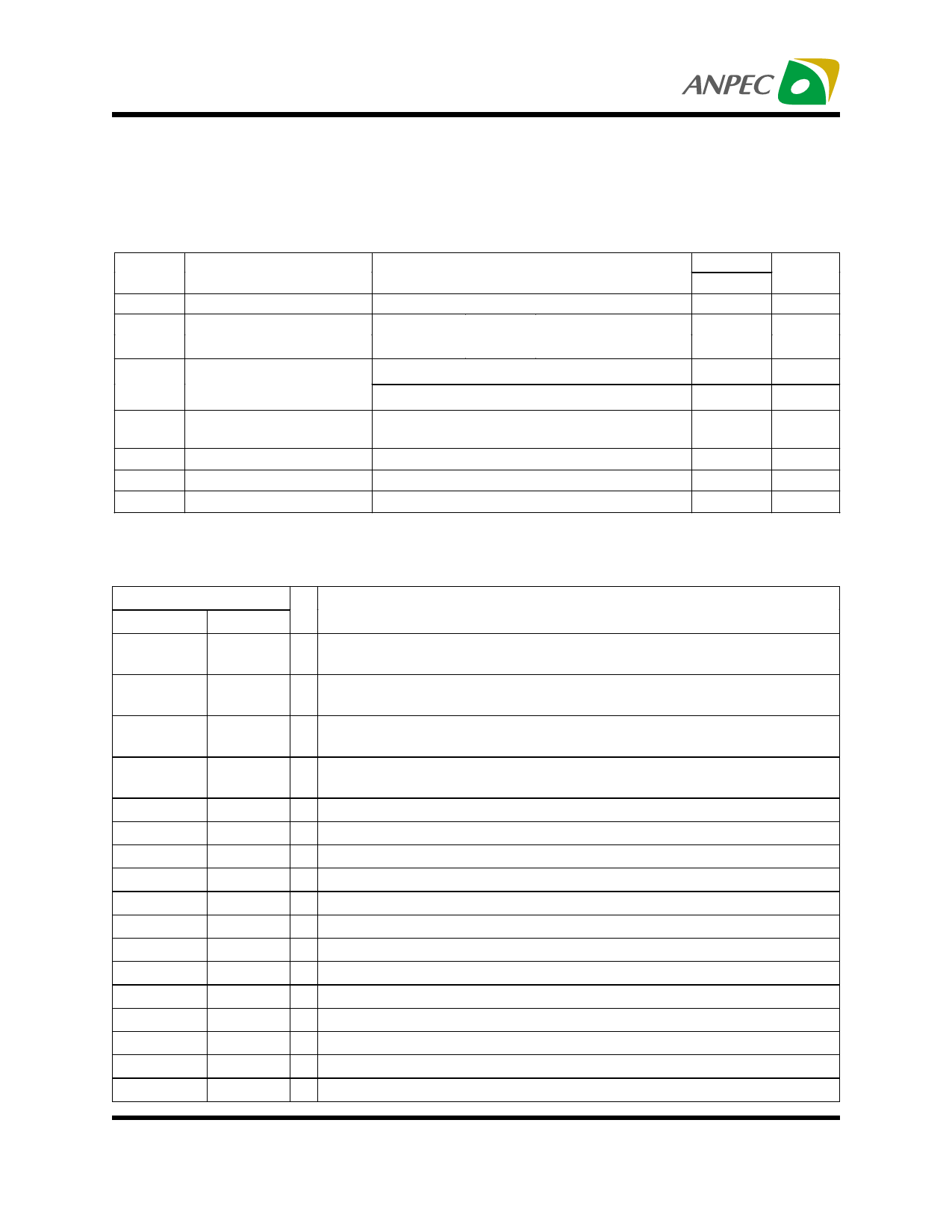
Electrical Characteristics (Cont.)
Electrical Characteristics for SE Mode Operation (Cont.)
The following specifications apply for VDD= 5V unless otherwise noted. Limits apply for TA= 25°C
Symbol
Parameter
Test Conditions
VOS
PO
THD+N
PSRR
XTALK
SNR
VN
Output Offset Voltage
Output Power
Total Harmonic Distortion
plus Noise
Power Supply Rejection
Ratio
Channel Separation
Signal-to-Noise Ratio
Output Noise Voltage
VIN=0V
THD=1%,
THD=10%,
f=1kHz, RL=32Ω
f=1kHz, RL=32Ω
AV= 1 , VOUT=1VRMS, RL=10kΩ, f=1kHz
PO =75mW, RL=32Ω, AV= 1, f=1kHz
VRIPPLE=100mVRMS , f=120Hz, CB=2.2µF
CB=2.2µF, RL=8Ω , f=1kHz
PO =75mW, RL=32Ω, A-Wtd Filter
RL=32Ω, A-Wtd Filter
APA4838
Typ.
5
95
110
0.05
0.07
52
90
102
20
Unit
mV
mW
%
%
dB
dB
dB
µV
Pin Description
Pin
Name
No
GND
1, 8, 14,
20, 23
Shutdown
2
Gain Select
3
Mode
4
Mute
VDD
DC_Vol
Right Dock
Right In
Beep In
Left In
Left Dock
Left Out +
Left Out -
Left Gain 2
Left Gain 1
HP Sense
5
6, 16, 27
7
9
10
11
12
13
15
17
18
19
21
I/O
Description
Ground connection for circuitry.
I Shutdown mode control signal input, place entire IC in shutdown mode when
held high, Idd=0.7uA
I Gain select input pin, logic high will switch the amplifier to external gain
mode, and logic low will switch to internal unity gain.
I Mode select input pin, fixed gain when logic L and gain adjustable mode
when logic H.
I Mute control input pin, active H.
Supply voltage input pin
I Volume control function input pin.
O Right docking output pin
I Right channel audio input pin
I Beep signal input pin
I Left channel audio input pin
O Right docking output pin
O Left channel positive output pin
O Left channel negative output pin
Connect pin 2 of the external gain setting resistor for left channel
Connect pin 1 of the external gain setting resistor for left channel
I Headphone sense control pin
Copyright ANPEC Electronics Corp.
5
Rev. A.1 - Apr., 2003
www.anpec.com.tw
Share Link: 