BD9006F-TR 查看數據表(PDF) - ROHM Semiconductor
零件编号
产品描述 (功能)
生产厂家
BD9006F-TR Datasheet PDF : 18 Pages
| |||
BD9006F, BD9006HFP, BD9007F, BD9007HFP
Technical Note
8. GND wiring pattern
It is recommended to separate the large-current GND pattern from the small-signal GND pattern and establish a single
ground at the reference point of the set PCB, so that resistance to the wiring pattern and voltage fluctuations due to a
large current will cause on fluctuations in voltages of the small-signal GND. Prevent fluctuations in the GND wiring pattern
of external parts.
9. Temperature protection (thermal shut down) circuit
This IC has a built-in temperature protection circuit to prevent the thermal destruction of the IC. As described above, be
sure to use this IC within the power dissipation range. Should a condition exceeding the power dissipation range continue,
the chip temperature Tj will rise to activate the temperature protection circuit, thus turning OFF the output power element.
Then, when the tip temperature Tj falls, the circuit will be automatically reset. Furthermore, if the temperature protection
circuit is activated under the condition exceeding the absolute maximum ratings, do not attempt to use the temperature
protection circuit for set design.
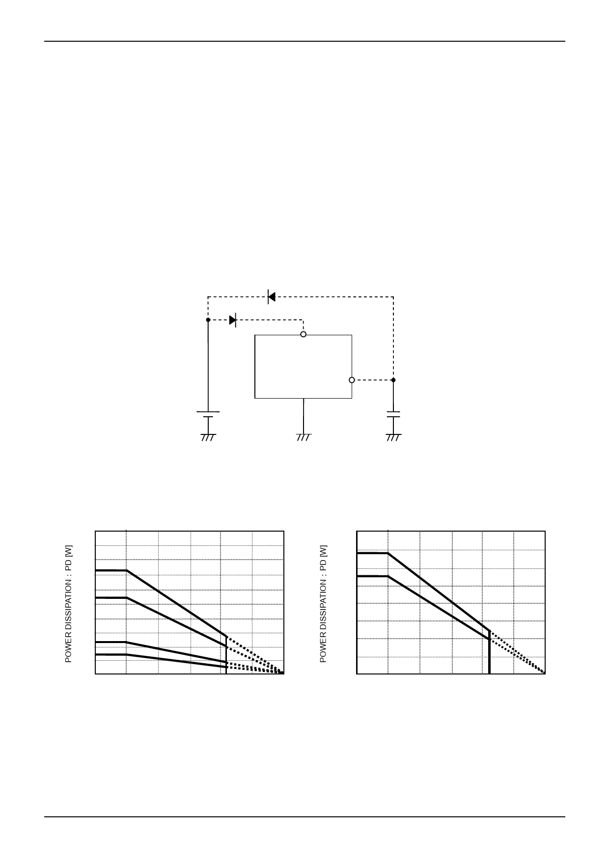
10. On the application shown below, if there is a mode in which VIN and each pin potential are inverted, for example, if the
VIN is short-circuited to the Ground with external diode charged, internal circuits may be damaged. To avoid damage, it is
recommended to insert a backflow prevention diode in the series with VIN or a bypass diode between each pin and VIN.
Bypass diode
Backflow prevention diode
Vcc
Pin
Fig.30
●Thermal reduction characteristics
HRP7
10
9
8 ④7.3W
7
6 ③5.5W
5
4
3 ②2.3W
2
1 ①1.4W
0
25
50
75 100 125 150
AMBIENT TEMPERATURE:Ta [℃]
① Single piece of IC
PCB Size: 70×70×1.6mm3 (PCB incorporates thermal via)
Copper foil area on the front side of PCB: 10.5×10.5mm2
② 2-layer PCB (Copper foil area on the reverse side of PCB: 15×15mm2)
③ 2-layer PCB (Copper foil area on the reverse side of PCB: 70×70mm2)
④ 4-layer PCB (Copper foil area on the reverse side of PCB: 70×70mm2)
Fig.31
SOP8
0.8
0.7 ②
0.6 ①
0.5
0.4
0.3
0.2
0.1
0
25
50
75 100 125 150
AMBIENT TEMPERATURE:Ta [℃]
① Single piece of IC
② When mounted on ROHM standard PCB
(Glass epoxy PCB of 70mm×70mm×1.6mm)
Fig.32
www.rohm.com
© 2009 ROHM Co., Ltd. All rights reserved.
16/17
2009.05 - Rev.A
Share Link: 