DS2764AX 查看數據表(PDF) - Maxim Integrated
零件编号
产品描述 (功能)
生产厂家
DS2764AX Datasheet PDF : 20 Pages
| |||
DS2764 High-Precision Li+ Battery Monitor With 2-Wire Interface
BL2—EEPROM Block 2 Lock Flag. A 1 in this read-only bit indicates that EEPROM block 2 (addresses 40 to 47) is
locked (read-only) while a 0 indicates block 2 is unlocked (read/write). The special order unique 64-bit ID device
does not support EEPROM Block 2.
BL1—EEPROM Block 1 Lock Flag. A 1 in this read-only bit indicates that EEPROM block 1 (addresses 30 to 3F) is
locked (read-only) while a 0 indicates block 1 is unlocked (read/write).
BL0—EEPROM Block 0 Lock Flag. A 1 in this read-only bit indicates that EEPROM block 0 (addresses 20 to 2F) is
locked (read-only) while a 0 indicates block 0 is unlocked (read/write).
X—Reserved Bits.
SPECIAL FEATURE REGISTER
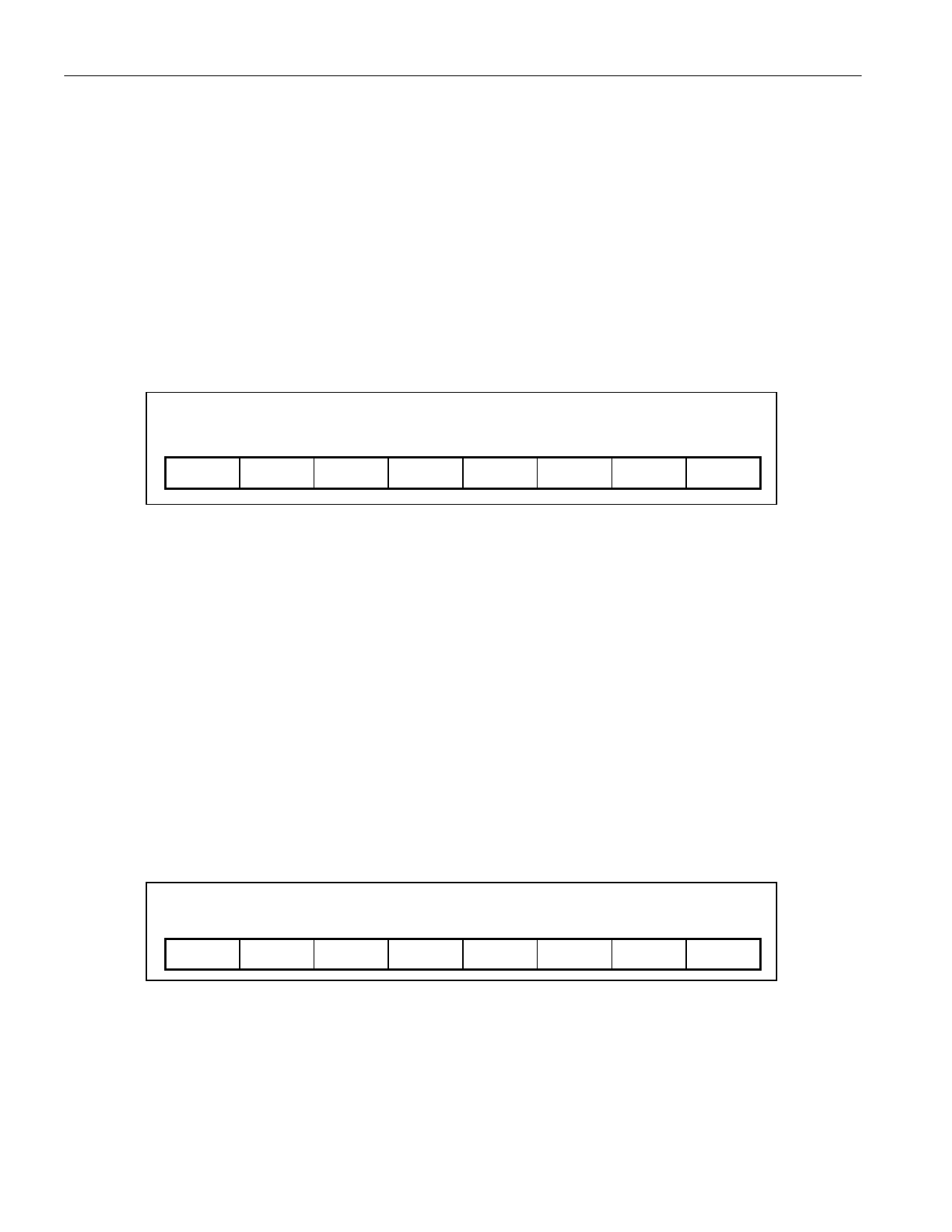
The format of the special feature register is shown in Figure 14. The function of each bit is described in detail in the
following paragraphs.
Figure 14. Special Feature Register Format
BIT 7
PS
BIT 6
X
BIT 5
X
ADDRESS 08
BIT 4 BIT 3
X
X
BIT 2
X
BIT 1
SAWE
BIT 0
X
PS¾PS Pin Latch. This bit latches a low state on the PS pin with a 0 value. The bit is cleared only by writing a 1 to
this location. See the Power Switch Input section.
SAWE¾Slave Address Write Enable. This bit must be set to 1 before the 2-wire slave address in location 0x32 can
be modified. SAWE should be written back to 0 after writing the slave address. Power up default is 0.
X¾Reserved Bits.
PROGRAMMABLE SLAVE ADDRESS
The 2-Wire slave address of the DS2764 is stored in lockable EEPROM block 1, address 32h. Programming the
slave address requires a write to set the SAWE bit in the Special Feature register, followed by a write to 32h with
the desired slave address. The new slave address value is effective following the write to 32h, and must be used
to address the DS2764 on subsequent bus transactions. The slave address value is not stored to EEPROM until a
Copy EEPROM block 1 command is executed. Prior to executing the Copy command, power cycling the DS2764
restores the original slave address value. The data format of the slave address value in address 32h is shown in
Figure 15.
Figure 15. Slave Address Format
BIT 7
A6
BIT 6
A5
BIT 5
A4
ADDRESS 32
BIT 4 BIT 3
A3
A2
BIT 2
A1
BIT 1
A0
BIT 0
X
A6 to A0—Slave Address. A6-A0 contains the 7-bit slave address of the DS2764. The factory default is
0110100b.
X—Reserved Bits.
16 of 20
Share Link: 