EL5156(2006) 查看數據表(PDF) - Intersil
零件编号
产品描述 (功能)
生产厂家
EL5156 Datasheet PDF : 17 Pages
| |||
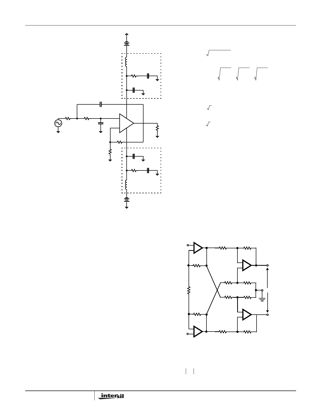
EL5156, EL5157, EL5256, EL5257
R1
V1
1kΩ
V2
5V
TUNED POWER
BYPASS NETWORK
L1
10µH
R5
C3
1kΩ 1nF
C5
1nF
C1
1nF
R2
1kΩ C2
1nF
+ V+
- V-
RB
1kΩ
RA
1kΩ
TUNED POWER
BYPASS NETWORK
C5
1nF
R6
1kΩ
L1
10µH
VOUT
R7
1kΩ
C4
1nF
V3
5V
Holp = K
wo =
1
R1C1R2C2
Q=
1
(1− K) R1C1 + R1C2 +
R2C2 R2C1
R2C2
R1C1
Holp = K
4−K
wo = 2
RC
Q= 2
4−K
Equations simplify if we let
all components be equal R=C
FIGURE 36. SULLEN KEY HIGH PASS FILTER
Differential Output Instrumentation Amplifier
The addition of a third amplifier to the conventional three
amplifier instrumentation amplifier introduces the benefits of
differential signal realization, specifically the advantage of
using common mode rejection to remove coupled noise and
ground potential errors inherent in remote transmission. This
configuration also provides enhanced bandwidth, wider
output swing and faster slew rate than conventional three
amplifier solutions with only the cost of an additional
amplifier and few resistors.
A1
e1
+
-
R2
RG
R3
R3
R3
R3
A3
-
eo3
+
+
R3
REF
R3
eo
R2
A4
-
+
-
eo4
A2
-
R3
R3
e2
+
eo3 = –(1 + 2R2 ⁄ RG)(e1 – e2) eo4 = (1 + 2R2 ⁄ RG)(e1 – e2)
eo = –2(1 + 2R2 ⁄ RG)(e1 – e2)
BW = 2----f--C----1---,---2-
ADi
ADi = –2(1 + 2R2 ⁄ RG)
13
FN7386.3
June 15, 2006
Share Link: 