MAX8600A 查看數據表(PDF) - Maxim Integrated
零件编号
产品描述 (功能)
生产厂家
MAX8600A
Maxim Integrated
MAX8600A Datasheet PDF : 12 Pages
| |||
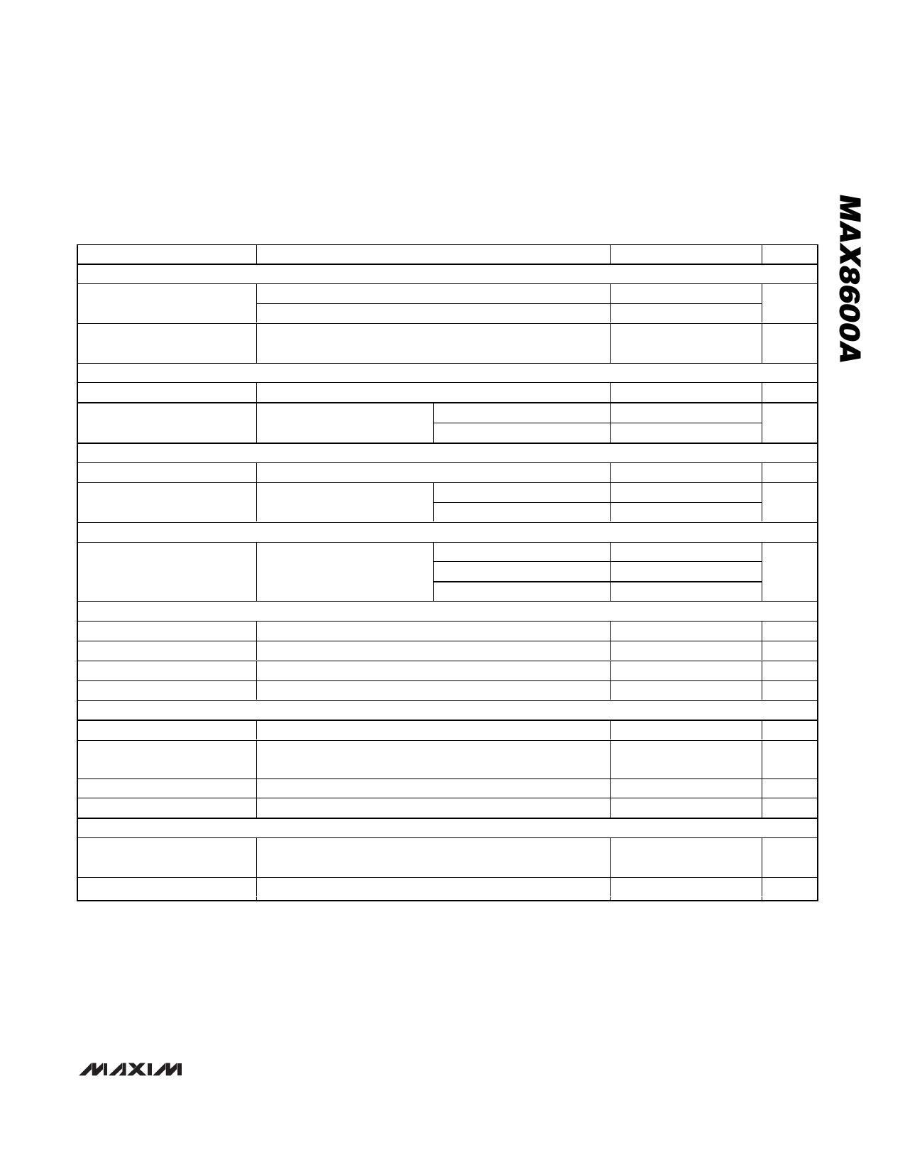
Single-Input 1-Cell Li+ Charger with
OVP Protection and Programmable Charge Timer
ELECTRICAL CHARACTERISTICS (continued)
(VDC = 5V, VBAT = 3.6V, V EN = 0V, RSETI = 2kΩ, CCT = 0.068µF, TA = -40°C to +85°C, unless otherwise noted. Typical values are at
TA = +25°C.) (Note 1)
PARAMETER
CONDITIONS
MIN TYP MAX UNITS
EN
Logic Input Thresholds
Rising
Falling
1.6
V
0.4
Logic Input Resistance to
GND
POK
Logic Output Voltage, Low
Logic Output Leakage
Current, High
CHG, FLT
Logic Output Voltage, Low
Logic Output Leakage
Current, High
CHG
CHG/Top-Off Current
Threshold
THM
THM Pullup Resistance
THM Resistance, Hot
THM Resistance, Cold
THM Resistance, Disabled
TIMERS, CT
Timer Accuracy
Prequal Time Limit
Charge Time Limit
Top-Off Time Limit
THERMAL LOOP
IPOK = 100µA
VPOK = VDC = 16V
TA = +25°C
TA = +85°C
ICHG = IFLT = 1mA
VCHG = VFLT = 5.5V,
VDC = 0V
TA = +25°C
TA = +85°C
IBAT falling, battery is
charged
RSETI = 1.5kΩ
RSETI = 2kΩ
RSETI = 5kΩ
Match to thermistor resistance at TA = +25°C
RTHM falling, 420Ω hysteresis
RTHM rising, 2.7kΩ hysteresis
RTHM falling, 230Ω hysteresis
CCT = 0.068µF
From POK low and EN low to end of prequal charge,
BAT < 2.4V, CCT = 0.068µF
From POK low and EN low to end of charge, CCT = 0.068µF
From CHG high to done, CCT = 0.068µF
250 485 1000
kΩ
29
100
mV
0.001 1
µA
0.01
12
100
mV
0.001 1
µA
0.01
60
30
45
60
mA
18
-1%
10 +1%
kΩ
3.72 3.94 4.13
kΩ
26.7 28.3 29.7
kΩ
240 309 370
Ω
-20
+20
%
34.8
min
334
min
69.6
min
Thermal-Limit Temperature
Thermal-Limit Gain
Junction temperature when the charge current is reduced,
TJ rising
Reduction of IBAT for increase of TJ, IBAT/TJ (over +100°C)
+100
5
°C
%/°C
Note 1: Limits are 100% production tested at TA = +25°C. Limits over the operating temperature range are guaranteed by design
and characterization.
Note 2: Guaranteed by undervoltage- and overvoltage-threshold testing. For complete charging, the input voltage must be greater
than 4.35V.
_______________________________________________________________________________________ 3
Share Link: 