JM38510/13903BIA 查看數據表(PDF) - Analog Devices
零件编号
产品描述 (功能)
生产厂家
JM38510/13903BIA Datasheet PDF : 8 Pages
| |||
AD532
AD532 PERFORMANCE CHARACTERISTICS
Multiplication accuracy is defined in terms of total error at
25°C with the rated power supply. The value specified is in
percent of full scale and includes XIN and YIN nonlinearities,
feedback and scale factor error. To this must be added such
application-dependent error terms as power supply rejection,
common-mode rejection and temperature coefficients (although
worst case error over temperature is specified for the AD532S).
Total expected error is the rms sum of the individual compo-
nents since they are uncorrelated.
Accuracy in the divide mode is only a little more complex. To
achieve division, the multiplier cell must be connected in the
feedback of the output op amp as shown in Figure 13. In this
configuration, the multiplier cell varies the closed loop gain of the
op amp in an inverse relationship to the denominator voltage.
Thus, as the denominator is reduced, output offset, bandwidth
and other multiplier cell errors are adversely affected. The divide
error and drift are then ⑀m × 10 V/X1 – X2) where ⑀m represents
multiplier full-scale error and drift, and (X1–X2) is the absolute
value of the denominator.
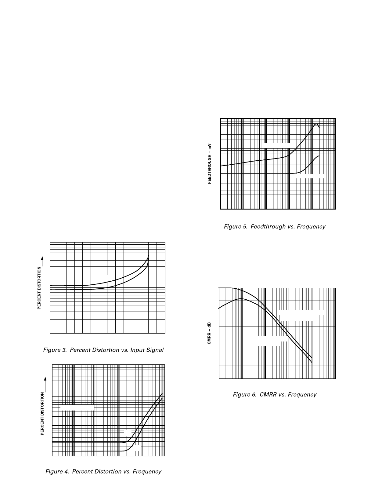
NONLINEARITY
Nonlinearity is easily measured in percent harmonic distortion.
The curves of Figures 3 and 4 characterize output distortion as
a function of input signal level and frequency respectively, with
one input held at plus or minus 10 V dc. In Figure 4 the sine
wave amplitude is 20 V (p-p).
1.0
XIN
YIN
0.1
0.01
1 2 3 4 5 6 7 8 9 10 11 12 13 14
PEAK SIGNAL AMPLITUDE ؊ Volts
Figure 3. Percent Distortion vs. Input Signal
100
10
20V p-p SIGNAL
AC FEEDTHROUGH
AC feedthrough is a measure of the multiplier’s zero suppression.
With one input at zero, the multiplier output should be zero
regardless of the signal applied to the other input. Feedthrough
as a function of frequency for the AD532 is shown in Figure 5. It
is measured for the condition VX = 0, VY = 20 V (p-p) and VY = 0,
VX = 20 V (p-p) over the given frequency range. It consists
primarily of the second harmonic and is measured in millivolts
peak-to-peak.
1000
Y FEEDTHROUGH
100
X FEEDTHROUGH
10
1
100
1k
10k
100k
1M
10M
FREQUENCY ؊ Hz
Figure 5. Feedthrough vs. Frequency
COMMON-MODE REJECTION
The AD532 features differential X and Y inputs to enhance its
flexibility as a computational multiplier/divider. Common-mode
rejection for both inputs as a function of frequency is shown in
Figure 6. It is measured with X1 = X2 = 20 V (p-p), (Y1 – Y2) =
10 V dc and Y1 = Y2 = 20 V (p-p), (X1 – X2) = 10 V dc.
70
60
50
Y COMMON-MODE REJ
(X1؊X2) ؍؉10V
40
30
X COMMON-MODE REJ
(Y1؊Y2) ؍؉10V
20
10
0
100
1k
10k
100k
1M
10M
FREQUENCY ؊ Hz
Figure 6. CMRR vs. Frequency
1.0
XIN
YIN
0.1
10
100
1k
10k
100k
1M
FREQUENCY ؊ Hz
Figure 4. Percent Distortion vs. Frequency
–4–
REV. C
Share Link: 