STW5094AD 查看數據表(PDF) - STMicroelectronics
零件编号
产品描述 (功能)
生产厂家
STW5094AD
STMicroelectronics
STW5094AD Datasheet PDF : 52 Pages
| |||
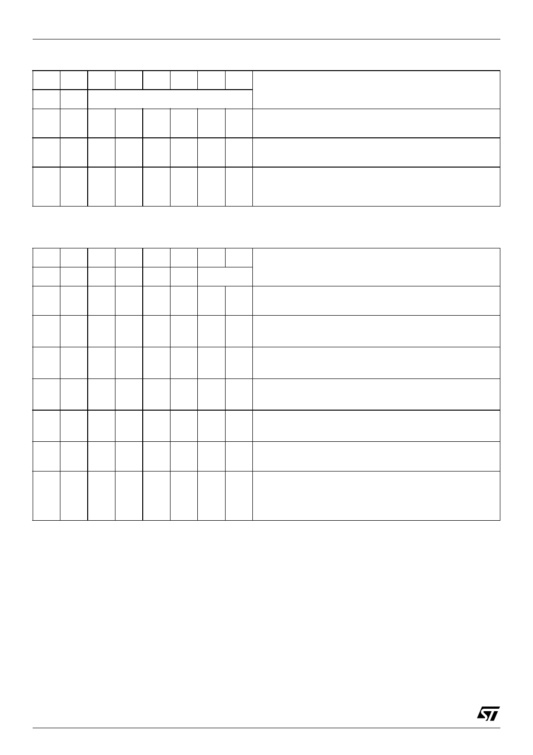
STw5094A
Control Register CR15 Functions (Address: 0x0F)
7
6
5
4
BE BI
0
1
0
1
msb
32
BZ(5:0)
* state at power on initialization
1
0
Function
Buzzer output disabled (set to 0)
*
Buzzer output enabled
Duty Cycle is intended as the relative width of logic 1 *
Duty cycle is intended as the relative width of logic 0
lsb Binary equivalent of the decimal number used to calculate the
duty cycle, using the formula:
Duty Cycle = BZ(5:0) x 0.78125%
Control Register CR16 Functions (Address: 0x10)
7
6
5
4
3
2
1
0
POL ORD DIF INV FOR SCL PREC(1:0)
Function
0
AMCK Not Inverted
*
1
AMCK Inverted
0
Audio I/F data order, the MSB is received first (I2S)
*
1
Audio I/F data order, the LSB is received first
0
Audio I/F data alignment, the word is left justified (I2S)(1) *
1
Audio I/F data alignment, the word is right justified (1)
0
LRCK polarity, when LRCK=0 Left data is received (I2S) (2) *
1
LRCK polarity, when LRCK=1 Left data is received
(2)
0
Audio I/F format, I2S format (first bit is delayed)
(3) *
1
Audio I/F format, non delayed formats
0
SCK polarity, SDI and LRCK sampled on the rising edge (I2S) *
1
SCK polarity, SDI and LRCK sampled on the falling edge
0
0 Audio I/F data width 16 bit (32 SCK clocks per frame) *
0
1 Audio I/F data width 18 bit (64 SCK clocks per frame)
1
0 Audio I/F data width 20 bit (64 SCK clocks per frame)
1
1 Audio I/F data width 24 bit (64 SCK clocks per frame)
(1) significant in 18 ⁄ 20 ⁄ 24 bit per word mode only
(2) Left Channel data is always received first.
(3) First bit delay, in 18 ⁄ 20 ⁄ 24 bit per word mode, is applied only if word is left justified.
*: state at power on initialization
20/51
Share Link: 