U2405B 查看數據表(PDF) - Temic Semiconductors
零件编号
产品描述 (功能)
生产厂家
U2405B Datasheet PDF : 17 Pages
| |||
U2405B
General Description
The integrated circuit, U2405B, is designed for charging
Nickel-Cadmium (NiCd) and Nickel-Metal-Hydride
(NiMH) batteries. Fast charging results in voltage lobes
when fully charged (figure 3). It supplies two
identifications ( i. e., + d2V/dt2, and – DV ) to end the
charge operation at the proper time.
* * As compared to the existing charge concepts where the
charge is terminated after voltage lobes according
to – DV and temperature gradient identification, the
U2405B takes into consideration the additional changes
in positive charge curves, according to the second
derivative of the voltage with respect to time (d2V/dt2).
The charge identification is the sure method of switching
off the fast charge before overcharging the battery. This
helps to give the battery a long life by hindering any
marked increase in cell pressure and temperature.
Even in critical charge applications, such as a reduced
charge current or with NiMH batteries where weaker
charge characteristics are present multiple gradient
control results in very efficient switch-off.
An additional temperature control input increases not
only the performances of the charge switching
characteristics but also prevents the general charging of
a battery whose temperature is outside the specified
window.
A specific preformation algorithm is implemented for
reactivating fully drained batteries especially in the case
of batteries that have been stored for a long time.
A constant charge current is necessary for continued
charge-voltage characteristic. This constant current
regulation is achieved with the help of internal amplifier
phase control and a simple shunt-current control tech-
nique.
All functions relating to battery management can be
achieved with DC-supply charge systems. A DC-DC-
converter or linear regulator should take over the function
of power supply. For further information please refer to
the applications.
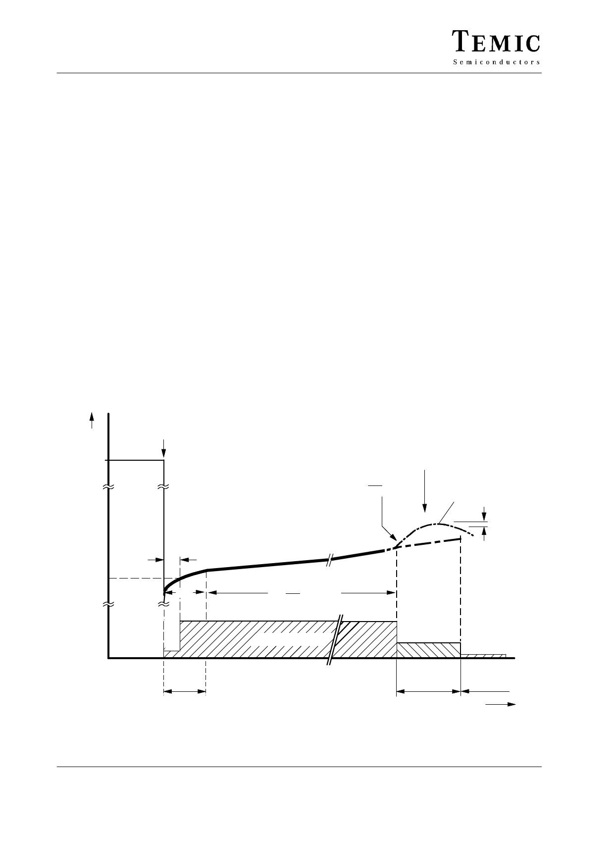
Battery
voltage
5V
Battery insertion
preformation
1.6 V
ÎΖDV
Fast charge stop
) d2V
dt2
Top-off charge stop
without
charge control
–DV
) D d2V
dt2
,
–
V
I (RB1)
95 10616
t1 = 5 min
Fast charge rate IO
Top-off
charge rate
1/4 IO
t2 = 20 min
Figure 3. Charge function diagram, fosc = 800 Hz
Trickle
charge rate
1/256 IO
t
4 (17)
TELEFUNKEN Semiconductors
Rev. A2, 14-Nov-96
Share Link: 