TS616 查看數據表(PDF) - STMicroelectronics
零件编号
产品描述 (功能)
生产厂家
TS616 Datasheet PDF : 37 Pages
| |||
TS616
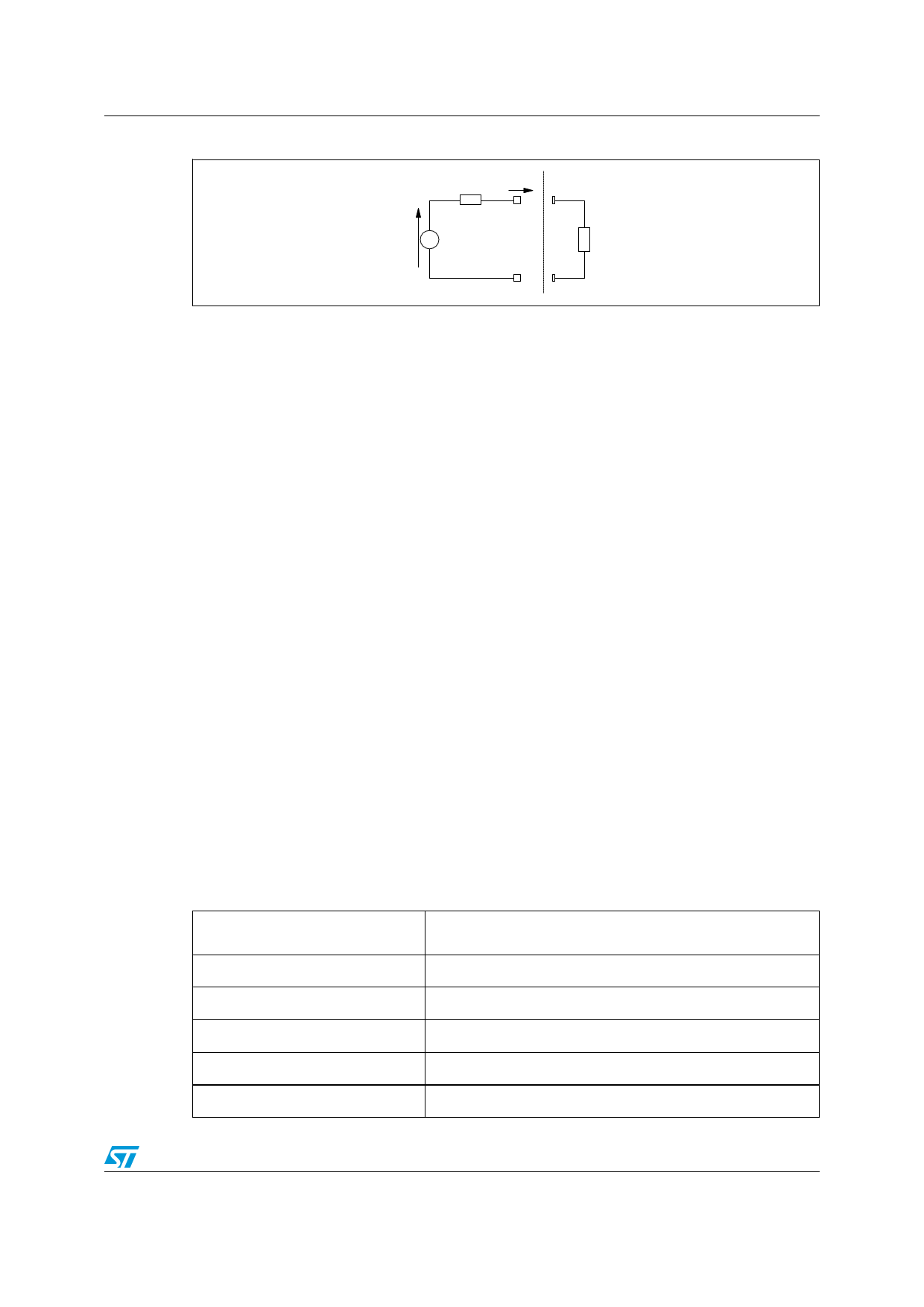
Increasing the line level using active impedance matching
Figure 70. Equivalent schematic - Ro is the synthesized impedance
Ro
Iout
Vi.Gi
1/2RL
Let us write Vo°=kVo, where k is the matching factor varying between 1 and 2. If we assume
that the current through R3 is negligible, we can calculate the output resistance, Ro:
Ro = ------k---V----o----R-----L------
RL + 2Rs1
After choosing the k factor, Rs will be equal to 1/2RL(k-1).
For a good impedance matching we assume that:
Equation 10
Ro = 12-- RL
From Equation 9 and Equation 10, we derive:
Equation 11
R-----2-- = 1 – 2----R-----s-
R3
RL
By fixing an arbitrary value of R2, Equation 11 becomes:
R3 = -------R-----2--------
1 – 2----R-----s-
RL
Finally, the values of R2 and R3 allow us to extract R1 from Equation 6, so that:
Equation 12
with GL the required gain.
R1 = ------------------------2----R-----2-------------------------
2
⎛
⎝
1
–
RR-----23--⎠⎞
GL
–
1
–
R-----2--
R3
Table 6. Components calculation for impedance matching implementation
GL (gain for the loaded system)
GL is fixed for the application requirements
GL= Vo/Vi= 0.5(1+2R2/R1+R2/R3)/(1-R2/R3)
R1
2R2/[2(1-R2/R3)GL-1-R2/R3]
R2 (= R4)
Arbitrarily fixed
R3 (= R5)
R2/(1-Rs/0.5RL)
Rs
0.5RL(k-1)
Load viewed by each driver kRL/2
33/37
Share Link: 