FZT689BTA 查看數據表(PDF) - Diodes Incorporated.
零件编号
产品描述 (功能)
生产厂家
FZT689BTA Datasheet PDF : 7 Pages
| |||
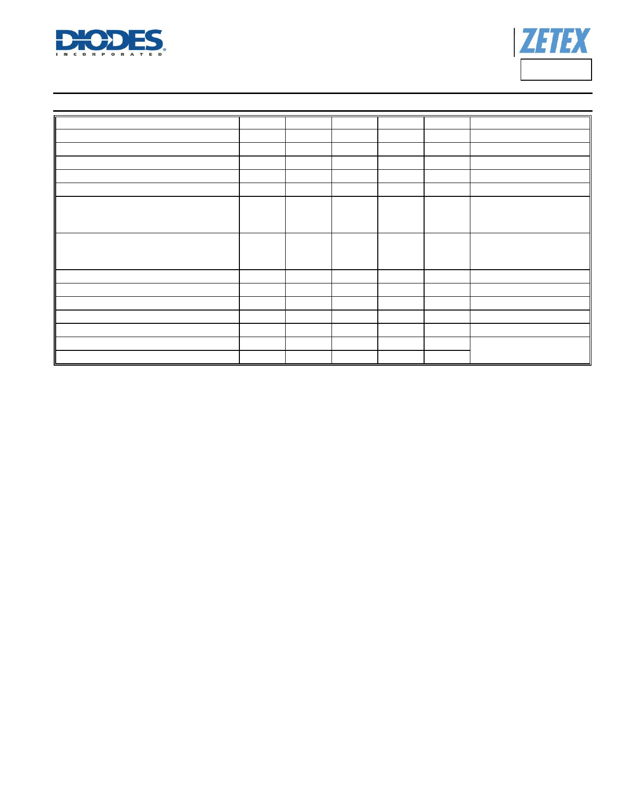
Electrical Characteristics (@TA = +25°C, unless otherwise specified.)
Characteristic
Symbol
Min
Typ
Collector-Base Breakdown Voltage
BVCBO
20
—
Collector-Emitter Breakdown Voltage (Note 11)
BVCEO
20
—
Emitter-Base Breakdown Voltage
Collector-Base Cut-Off Current
Emitter Cut-Off Current
BVEBO
7
—
ICBO
—
—
IEBO
—
—
DC Current Gain (Note 11)
500
—
hFE
400
—
150
—
—
—
Collector-Emitter Saturation Voltage (Note 11)
VCE(sat)
—
—
—
—
Base-Emitter Saturation Voltage (Note 11)
Base-Emitter Turn-On Voltage (Note 11)
Input Capacitance
Output Capacitance
Current Gain-Bandwidth Product
Turn-On Time
Turn-Off Time
VBE(sat)
—
—
VBE(on)
—
—
Cibo
—
200
Cobo
—
16
fT
150
—
ton
—
30
toff
—
800
Note:
11. Measured under pulsed conditions. Pulse width ≤ 300 µs. Duty cycle ≤ 2%.
A Product Line of
Diodes Incorporated
FZT689B
5
Max
—
—
—
0.1
0.1
—
—
—
0.10
0.50
0.45
0.9
0.9
—
—
—
—
—
Unit
V
V
V
µA
µA
—
V
V
V
pF
pF
MHz
ns
ns
Test Condition
IC = 100µA
IC = 10mA
IE = 100µA
VCB = 16V
VEB = 5.6V
IC = 0.1A, VCE = 2V
IC = 2A, VCE = 2V
IC = 6A, VCE = 2V
IC = 0.1A, IB = 0.5mA
IC = 2A, IB = 10mA
IC = 3A, IB = 20mA
IC = 1A, IB = 10mA
IC = 1A, VCE = 2V
VEB = 0.5V, f = 1MHz
VCB = 10V, f = 1MHz
VCE = 5V, IC = 50mA, f=50MHz
VCC = 10V, IC = 500mA
IB1 = -IB2 = 50mA
FZT689B
Document number: DS33155 Rev. 4 - 2
4 of 7
www.diodes.com
May 2015
© Diodes Incorporated
Share Link: 