IL66B(2004) 查看數據表(PDF) - Vishay Semiconductors
零件编号
产品描述 (功能)
生产厂家
IL66B Datasheet PDF : 5 Pages
| |||
IL66B
Vishay Semiconductors
Switching Characteristics
Parameter
Turn-On, Turn-Off time
Test condition
VCC = 10 V, IF = 2 mA,
RL = 100 Ω
Symbol
Min
Typ.
Max
Unit
ton, toff
200
µs
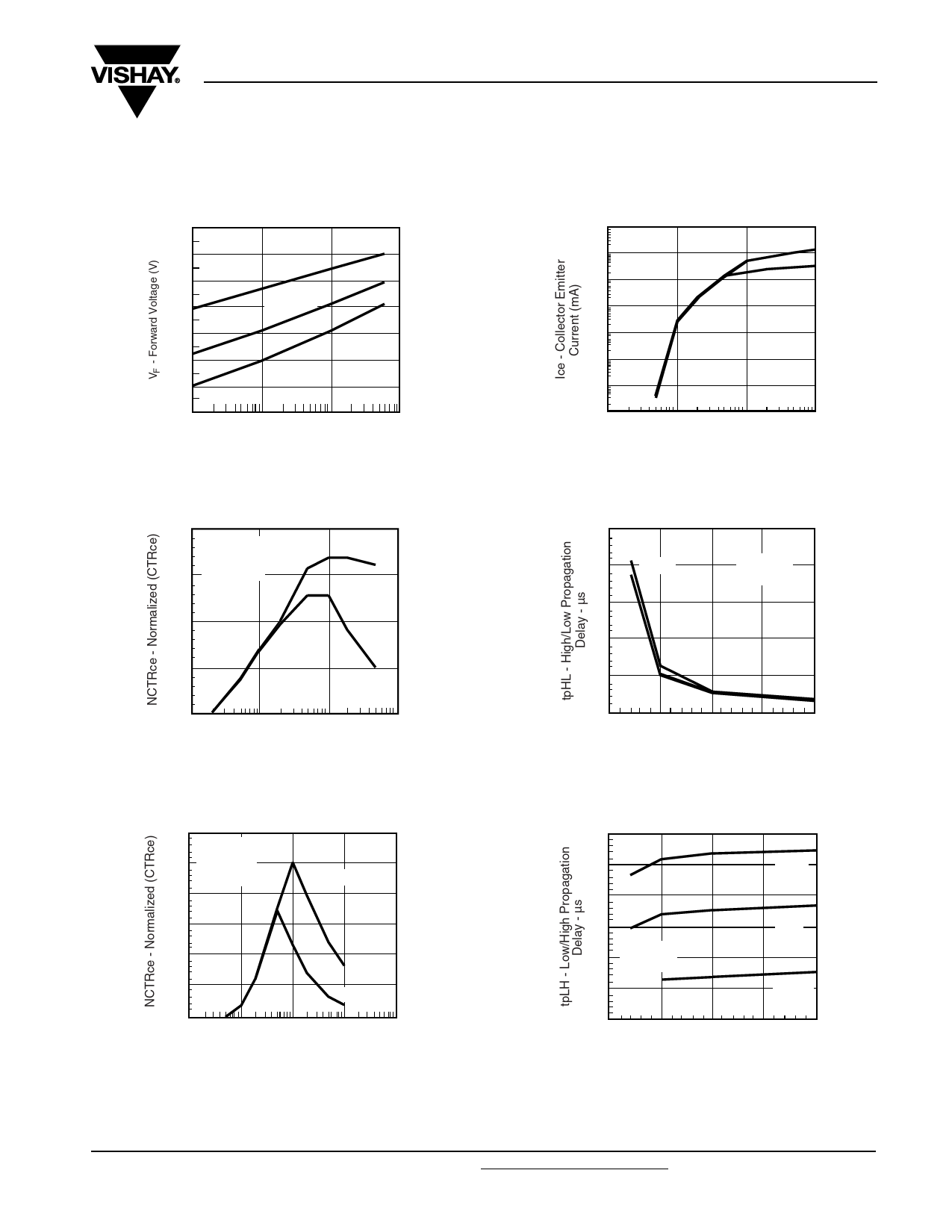
Typical Characteristics (Tamb = 25 °C unless otherwise specified)
1.4
1. 3
Ta = –55°C
1.2
1.1
Ta = 25°C
1.0
0.9
Ta = 85°C
0.8
0.7
.1
iil66b_01
1
10
100
IF - Forward Current - mA
Figure 1. Forward Voltage vs. Forward Current
10000
1000
Vce = 5 V
100
Vce = .4 V
10
1
.1
.01
.001
.1
1
10
100
IF - LED Current - mA
iil66b_04
Figure 4. Non-Saturated and Saturated Collector Emitter Current
vs. LED Current
2.0
Normalized to:
Vce = 5 V
1.5
IF = 2 mA
1.0
Vce = 5 V
0.5
Vce = 1 V
0.0
.1
iil66b_02
1
10
10 0
IF - LED Current - mA
Figure 2. Normalized Non-saturated and Saturated CTRCE vs.
LED Current
50
40
10 KıΩ
30
20 220 ıΩ
Vcc = 5 V
Vth = 1.5 V
10
0
0
iil66b_05
5
10
15
20
IF - LED Current - mA
Figure 5. High to low Propagation Delay vs. Collector Load
Resistance and LED Current
1.2 Normalized to:
1.0
Vce = 5 V
0.8
IF = 10 mA
Vce = 5 V
0.6
0.4
0.2
Vce = .4 V
0.0
.1
1
10
100
1000
iil66b_03
IF - LED Current - mA
Figure 3. Normalized Non-saturated and Saturated CTRCE vs.
LED Current
150
125
10 KΩ
100
75
Vcc = 5 V
50
Vth = 1.5 V
25
2 KΩ
220 KΩ
0
0
iil66b_06
5
10
15
20
IF - LED Current - mA
Figure 6. Low to High Propagation Delay vs. Collector Load
Resistance and LED Current
Document Number 83639
Rev. 1.5, 26-Oct-04
www.vishay.com
3
Share Link: 