NTE1130 查看數據表(PDF) - NTE Electronics
零件编号
产品描述 (功能)
生产厂家
NTE1130 Datasheet PDF : 3 Pages
| |||
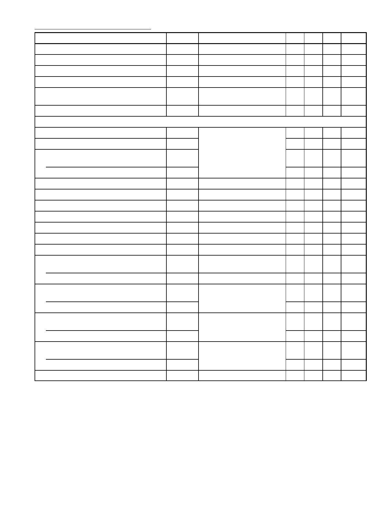
Electrical Characteristics (Cont’d): (TA = +25°C, VCC = 15V, RL = 5.6kΩ unless otherwise specified)
Parameter
Symbol
Test Conditions
Min Typ Max Unit
Chroma Signal Input Terminal Voltage
Sub–Carrier Signal Input Terminal Voltage
Difference Voltage Between Terminals
Output Voltage Temperature Coefficient
Output Difference Voltage Temperature
Coefficient
V4
RL = 5.6kΩ
V10 RL = 5.6kΩ
RL = 5.6kΩ
RL = 5.6kΩ
RL = 5.6kΩ
– 3.8 –
V
– 1.35 –
V
– – 0.4 V
–3.0 – +3.0 mV/°C
–2.0 – +2.0 mV/°C
Hue Circuit Output Current
Dynamic Characteristics (f = 3.58MHz)
I12 Pin9: Open
– 2.1 – mA
R–Y Output Voltage
G–Y Output Voltage
Relative Output Phase
R–Y to B–Y Output
G–Y to B–Y Output
B–Y Output Voltage
Chroma Signal Input Voltage
Harmonic Output Voltage
Residual Carrier Level
Hue Output Regulation
VR–Y
VG–Y
VB–Y = 2.5VP–P, er = 0.5VP–P 1.9 2.1 2.3
0.5 0.6 0.7
VP–P
VP–P
qR
qG
VB–Y
eC
eR = 0.5VP–P, eC = 1.0VP–P
VB–Y = 2.5VP–P, eR = 0.5VP–P
VB–Y = 2.5VP–P
eC = 0, eR = 0.5VP–P
Max/Min
110 115 120
247 255 263
4.5 6.0 –
– 200 300
– – 0.6
– 50 300
– – 1.7
deg.
deg.
VP–P
VP–P
VP–P
VP–P
Hue Max. Output Swing
Hue Phase Shift
ei = 1.0VP–P
Pin9: 0 to 15V
2.0 – –
70 100 –
VP–P
deg.
Sub–Carrier Terminal Input Impedance
Parallel Input Resistance
Parallel Input Capacitance
Reference Signal Terminal Input Impedance
Parallel Input Resistance
Parallel Input Capacitance
Chroma Signal Terminal Input Impedance
Parallel Input Resistance
Parallel Input Capacitance
Hue Circuit Terminal Input Impedance
Parallel Input Resistance
Parallel Input Capacitance
Hue Circuit Voltage Gain
rip
cip
rip
Pin1, Pin2
cip
rip
Pin5, Pin6
cip
rip
Pin12
cip
GVH RL = 1kΩ
– 2.1 – kΩ
– 4.0 –
pF
– 2.0 – kΩ
– 4.0 –
pF
– 2.0 – kΩ
– 4.0 –
pF
– 100 – kΩ
–6–
pF
5 9 13 dB
Share Link: 