SFH6732 查看數據表(PDF) - Vishay Semiconductors
零件编号
产品描述 (功能)
生产厂家
SFH6732 Datasheet PDF : 10 Pages
| |||
www.vishay.com
End of Life July-2017
SFH6731, SFH6732
Vishay Semiconductors
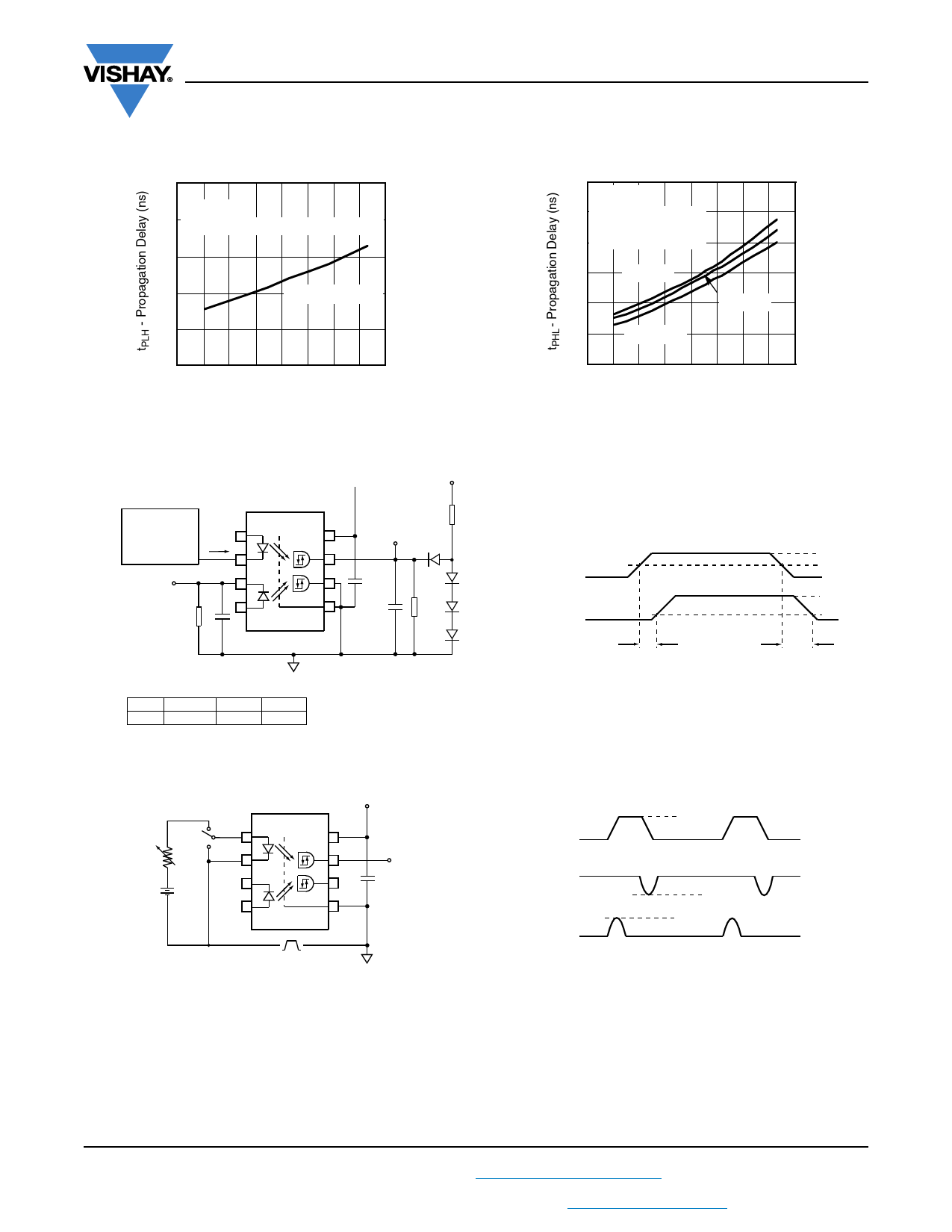
80
70
VCC = 15 V
C1 = 120 pF (without peaking capacitor)
60
50
IF = 1.6, 3 and 5 mA
40
30
- 60 - 40 - 20 0 20 40 60 80 100
isfh6731_17 TA - Temperature (°C)
Fig. 17 - Typical Propagation Delays to Logic High vs. Temperature
180
VCC = 15 V
160 C1 = 120 pF (peaking
140 capacitor is used)
120
IF = 5 mA
100
IF = 3 mA
80
IF = 1.6 mA
60
- 60 - 40 - 20 0 20 40 60 80 100
isfh6731_18 TA - Temperature (°C)
Fig. 18 - Typical Propagation Delays to Logic Low vs.Temperature
Pulse generator
tr, tf = 5 ns
f = 100 kHz
10% Duty cycle
Input IF
monitoring
node
1
IF
2
3
4
VCC 8
7
6
VCC
5V
R3 = 619 Ω
Output VO
monitoring
node
D1
0.1 µF
D2
Bypass
5
D3
GND
D4
Input IF
Output VO
R1 C1 = 120 pF
The Probe and Jig Capacitances are included in C1 and C2
R1
IFon
2.15 kΩ
1.6 mA
1.1 kΩ
3 mA
681 Ω
5 mA
C2 = 15 pF R2 = 5 kΩ
All diodes are 1N916 or 1N3064
Fig. 19 - Test Circuit for tPLH
tPLH
IFon
50 %IFon
0 mA
VOH
1.3 V
VOL
tPHL
isfh6731_19
VCC
A
1
R
B
2
3
4
VCC 8
7
6
5
Gnd
Output VO
monitoring
node
0.1 µF
bypass
+
Pulse generator
–
VCM
VCM
0V
VOH
Output VO
VOL
400 V/50 V
Switch at A: IF = 1.6 mA
VO (min.)
VO (max.)
Switch at B: IF = 0 mA
Fig. 20 - Test Circuit for Common Mode Transient Immunity and Typical Waveforms
isfh6731_20
Rev. 1.8, 07-Feb-17
7
Document Number: 83685
For technical questions, contact: optocoupleranswers@vishay.com
THIS DOCUMENT IS SUBJECT TO CHANGE WITHOUT NOTICE. THE PRODUCTS DESCRIBED HEREIN AND THIS DOCUMENT
ARE SUBJECT TO SPECIFIC DISCLAIMERS, SET FORTH AT www.vishay.com/doc?91000
Share Link: 